
Instruction Manual

DQ-4000 DQ-4000 User's Guide
Page: 8 / 21
P/N : 033-02061 Rev. 1
Table of Contents
1 INTRODUCTION........................................................................................................................9
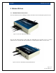
2 MODULE DETAILS..................................................................................................................10
2.1 DQ-4000 External Connections........................................................................................10
2.2 DQ-4000 Mechanical Dimensions ....................................................................................11
3 OPERATION GUIDE................................................................................................................12
3.1 Install the software driver for the device ...........................................................................12
3.2 Attach Loadstar frequency-based load cells to the sensor input ports .............................12
3.3 Connect the uplink port to your computer’s USB port.......................................................13
3.4 Communicate with the DQ-4000 ......................................................................................13
3.5 Terminal command line operation ....................................................................................14
4 COMMAND SUMMARY...........................................................................................................15
4.1 S# Command....................................................................................................................15
4.2 CT0 & CT1 Commands ....................................................................................................16
4.3 O0S0 & O0S1 Commands ...............................................................................................16
4.4 O0W0 and O0W1 Commands..........................................................................................17
4.5 O0X0 & O0X1 Commands ...............................................................................................17
4.6 O0T0 & O0T1 Commands................................................................................................17
4.7 CSS (Sample Size) Command .........................................................................................18
4.8 CPS (Packet Size) Command ..........................................................................................18
4.9 SLC (Load Capacity) Command.......................................................................................19
4.10 CN0, CN1, CP0, CP1, CAZ, FAZ, CLA & CTA Commands .............................................19
4.11 CK0 Command.................................................................................................................19
4.12 CS0 & CS1 (ID Strings) Commands.................................................................................20
4.13 FIT Command...................................................................................................................20
4.14 CQA, CQB, CQC, TQA, TQB & TQC Commands............................................................20
4.15 CCA, CCB, CCC, CCD, TCA, TCB, TCC & TCD Commands ..........................................21
4.16 SST (Sensor Status) Command .......................................................................................21
4.17 SETTINGS Command......................................................................................................21
List of Figures
Figure 1: Front View – With Sensors Attached................................................................................10
Figure 2: Rear View – With DC-IN and USB Uplink attached..........................................................10
Figure 3: Mechanical Top Dimension ..............................................................................................11
Figure 4: Mechanical Front Dimension ............................................................................................11
Figure 5: Front View – Sensor Input Ports.......................................................................................12
Figure 6: Back View – DC-IN, USB Uplink, LCD Contrast & Pushbutton ........................................13