48089 Fremont Blvd Fremont, CA 94538 (510) 623-9600 www.loadstarsensors.com DQ-4000 4 Channel Frequency-to-Digital Load Cell Interface User's Guide Copyright © 2009 Loadstar Sensors, Inc. All Rights Reserved.
DQ-4000 DQ-4000 User's Guide Notes © Copyright 2009 Loadstar Sensors, Inc. All Rights Reserved. No part of this manual may be reproduced in any form or by any means (including electronic storage and retrieval, or translation into a foreign language) without prior agreement and written consent from Loadstar Sensors, Inc. as governed by United States and international copyright laws. Manual Part Number 033-02061-Rev1 (September 2009) Loadstar Sensors Inc.
DQ-4000 DQ-4000 User's Guide Sensors reserves the right to make changes to its products at any time in the future. The specifications mentioned in this document are provided as guidelines only and may change in the future to reflect changes in design and availability of better test data. Copyright © Loadstar Sensors, Inc. 2005-2009. Repair Pricing Policy A nonrefundable analysis charge of $150.00 will be made on each out-of-warranty product returned to Loadstar Sensors for repair.
DQ-4000 DQ-4000 User's Guide WARNING 1. Do not use the DQ-4000 with the cover, or part of the cover removed or loose, as a hazardous condition may result. Inspect the case for cracks or missing plastic. Do not use if the DQ-4000 is damaged. 2. Use only Loadstar recommended AC Adapter, which conforms to the DQ-4000 required voltage and current ratings. 3. Do not operate the DQ-4000 in an explosive atmosphere, or in the presence of flammable gases or fumes. 4.
DQ-4000 DQ-4000 User's Guide ROHS/WEEE COMPLIANCE STATEMENT EUROPE Directive 2002/95/EC. Restriction of the Use of Certain Hazardous Substances in Electrical & Electronic Equipment, as amended by EU Commission Decision 2005/95/EC. This product is RoHS Compliant 2005/95/EC.
DQ-4000 DQ-4000 User's Guide WEEE Directive (2002/96/EC) The Waste Electrical and Electronic Equipment Directive (WEEE) applies to companies that manufacture, sell, and distribute electrical and electronic equipment in the E.U. It covers a wide range of large and small household appliances, IT equipment, radio and audio equipment, electrical tools, telecommunications equipment, electrical toys, etc.
DQ-4000 DQ-4000 User's Guide ROHS in China Electronic Industry Standard of the People’s Republic of China, SJ/T11363-2006. Requirements for Concentration Limits for Certain Hazardous Substances in Electronic Information Products.
DQ-4000 DQ-4000 User's Guide Table of Contents 1 2 3 4 INTRODUCTION........................................................................................................................9 MODULE DETAILS..................................................................................................................10 2.1 DQ-4000 External Connections........................................................................................10 2.2 DQ-4000 Mechanical Dimensions ..............................
DQ-4000 DQ-4000 User's Guide 1 INTRODUCTION The Loadstar Sensors DQ-4000 4-Channel Frequency to USB module provides a convenient method to convert the outputs from up to four of Loadstar’s frequency-output load cells into a PC friendly USB digital output. Attach the cable of iLoad-Mini (or other Loadstar frequency load cells) to one of the four sensor input ports on the DQ-4000 and connect the USB uplink output to your computer’s USB port for a complete Windows PC based weighing system.
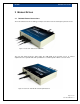
DQ-4000 DQ-4000 User's Guide 2 MODULE DETAILS 2.1 DQ-4000 External Connections The front view below shows 4 USB Type-B input connections for the iLoad frequency-based sensors. Figure 1: Front View – With Sensors Attached The rear view below shows the power input, the USB uplink to the host PC, access to contrast adjustment for the optional LCD, and a pushbutton to scroll through the LCD or to tare the load. Figure 2: Rear View – With DC-IN and USB Uplink attached Page: 10 / 21 P/N : 033-02061 Rev.
DQ-4000 2.2 DQ-4000 User's Guide DQ-4000 Mechanical Dimensions 130.0 mm (5.12”) 100.0 mm (3.94”) Figure 3: Mechanical Top Dimension 130.0 mm (5.12”) 30.8 mm (1.21”) Figure 4: Mechanical Front Dimension Page: 11 / 21 P/N : 033-02061 Rev.
DQ-4000 DQ-4000 User's Guide 3 OPERATION GUIDE 3.1 Install the software driver for the device If ordered without LoadVUE software, the DQ-4000 is shipped with a software driver installation disc. Please follow the instructions in the accompanying document to install the driver before you connect the DQ-4000 to your PC. If you ordered the DQ-4000 with LoadVUE, the LoadVUE disc contains the drivers. Please install LoadVUE and follow the onscreen instructions to also load the drivers. 3.
DQ-4000 3.3 DQ-4000 User's Guide Connect the uplink port to your computer’s USB port The picture below shows the back view of the DQ-4000. The host PC’s USB port is sufficient to power the DQ-4000 and up to 4 frequency load cells, external DC-IN is not required. If you ordered the DQ-4000 with ZigBee, LCD or battery backup option(s), a power adapter will be included. Plug the power-jack into DC-IN connector. The DC-IN power requirement is 9VDC12VDC at 2W, with Positive VDC on the center pin.
DQ-4000 3.5 DQ-4000 User's Guide Terminal command line operation Once you are connected to the DQ-4000 via HyperTerminal or another terminal emulation program, press [Enter] several times. You should get an “A” returned on your PC monitor screen for every [Enter] pressed. You may now issue ASCII commands to the DQ-4000, to remotely monitor and control the attached sensors. You may press “?” at any time to see the available command list.
DQ-4000 DQ-4000 User's Guide 4 COMMAND SUMMARY Except as noted, the commands for the DQ-4000 can all be entered without parameters to have the DQ-4000 report back the value of the appropriate parameters in memory. For example, issuing CS1 M3-2598 [Enter] sets the string1 to “M3-2598”. Now issuing CS1 [Enter] gets the DQ-4000 to respond with the currently set value, i.e. M3-2598.
DQ-4000 DQ-4000 User's Guide 4.2 CT0 & CT1 Commands Function: Tares (zero) the selected load cell Summary: The load on the selected load cell is set as the zero values and all subsequent load readings are relative to this gross zero value. CT0 is a “hard” tare that saves the values to the flash memory. While CT1 is a “soft” tare that the value is not preserved when the power is lost. The commands are issued without any other parameters.
DQ-4000 DQ-4000 User's Guide 4.4 O0W0 and O0W1 Commands Function: Output the gross load for the currently selected channel Summary: These commands output the load of the currently selected channel(s).The load is relative to the gross tare set by previous CT0 or CT1 command. The data is output in a single column: Computed load (millipounds). O0W0 outputs the data continuously, while O0W1 outputs it once. The streaming data generated by an O0W0 can be stopped by pressing [Enter].
DQ-4000 DQ-4000 User's Guide CONF COMMANDS CAUTION: The following commands are used to set the configuration of the DQ-4000 and should not be changed until you have a thorough understanding of the operation of the instrument and the effect of these parameters. The DQ-4000 would display erroneous load, if the parameters are not set correctly. 4.
DQ-4000 DQ-4000 User's Guide 4.9 SLC (Load Capacity) Command Function: Sets (or reports) load capacity of the load cell on the selected channel Summary: Sets or reports the load capacity of the currently selected channel using S1, S2, S3 or S4 command. If S0 command was previously issued, SLC would return the total load capacity of all channels. Example: SLC 50 (sets load capacity to 50 lb) SLC (reports current load capacity in lb) 4.
DQ-4000 DQ-4000 User's Guide 4.12 CS0 & CS1 (ID Strings) Commands Function: Sets (or reports) the value of two user settable ID strings, S0 and S1 Summary: Two user settable strings are provided for each channel of the DQ-4000. At the factory, CS0 is usually set to the Product Number of the load cell that is to be used with each channel, and CS1 is set to a condensed version of the unit serial number. The strings CS0 and CS1 may be 15 characters long.
DQ-4000 DQ-4000 User's Guide 4.15 CCA, CCB, CCC, CCD, TCA, TCB, TCC & TCD Commands Function: Set (or report) cubic fit parameters for selected channel Summary: Use these commands to set or list the various parameters for a cubic fit. Typically, these values will be provided to you by Loadstar based on a factory calibration. Also, typically the parameters for the compression side and the tension side are the same (e.g., CQA and TQA will have identical values).