
Manual

DI-100 User's Guide
Page: 9 / 19
P/N : 033-02205-Rev2
3 STEP BY STEP OPERATING GUIDE
3.1 Attach the Load Cell to the DI-100
If you have ordered a load cell with the DI-100, we would have made the load cell attachment to
the DI-100 for you. Please skip the following steps and go directly to next section (Install Virtual
COM Port Drivers).
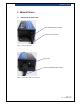
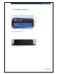
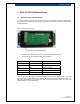
Figure 5: DI-100 (before assembly)
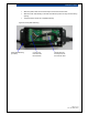
• Route the load cell cable through the opening of the strain relief bushing.
• Connect the wires per the wiring table as shown below.
Name Color Code Description
+SIG Green Output Signal Positive
-SIG White Output Signal Negative
+EXC Red Excitation Positive
-EXC Black Excitation Negative
SHLD Bare wire Shield
The color code as shown above is commonly used by many load cell manufacturers. If your load
cell manufacturer uses a different color scheme, please match the signal descriptions with your
load cell’s documentation. For 6-Wire load cells, connect the “Sense Positive” to +EXC, and
“Sense Negative” to -EXC respectively.
Opening for Strain Relief Bushing