
Manual

DI-100 User's Guide
Page: 5 / 19
P/N : 033-02205-Rev2
Table of Contents
1 INTRODUCTION ......................................................................................................................6
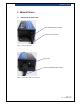
2 MODULE DETAILS ..................................................................................................................7
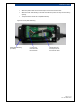
2.1 External DI-100 Connection ..............................................................................................7
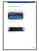
2.2 DI-100 Mechanical Dimensions.........................................................................................8
3 STEP BY STEP OPERATING GUIDE ......................................................................................9
3.1 Attach the Load Cell to the DI-100 ....................................................................................9
3.2 Install Virtual COM Port Drivers.......................................................................................11
3.3 Connecting DI-100 to Host PC ........................................................................................11
3.4 Terminal Command Line Operation.................................................................................11
3.5 DI-100 Initial Setup..........................................................................................................12
4 CALIBRATING THE DI-100 ....................................................................................................13
4.1 Calibration Mode .............................................................................................................13
4.2 Millivolt-per-Volt (mV/V) Calibration.................................................................................13
4.3 2-Point Calibration...........................................................................................................14
5 DI-100 COMMAND SUMMARY..............................................................................................15
5.1.1 UNIT ©....................................................................................................................15
5.1.2 LC ©........................................................................................................................15
5.1.3 ID ©.........................................................................................................................15
5.1.4 TARE ©...................................................................................................................16
5.1.5 CAL © .....................................................................................................................16
5.1.6 mVOLT ©................................................................................................................16
5.1.7 2PCAL © .................................................................................................................16
5.1.8 W ©.........................................................................................................................17
5.1.9 WC © ......................................................................................................................17
5.1.10 R © .....................................................................................................................17
5.1.11 RC ©...................................................................................................................17
5.1.12 SETTINGS © ......................................................................................................18
5.1.13 ? © ......................................................................................................................18
6 DI-100 TECHNICAL SPECIFICATIONS .................................................................................19
List of Figures
Figure 1: Load Cell Input Port........................................................................................................... 7
Figure 2: Power LED & USB Host Connection .................................................................................7
Figure 3: Mechanical Top View ........................................................................................................8
Figure 4: Mechanical Front View ......................................................................................................8
Figure 5: DI-100 (before assembly) .................................................................................................. 9
Figure 6: DI-100 (after assembly)................................................................................................... 10
Figure 7: USB connection to host PC .............................................................................................11