48089 Fremont Blvd Fremont, CA 94538 (510) 623-9600 www.loadstarsensors.com DI-100 16-Bit Digital Load Cell Interface User's Guide Copyright © 2010 Loadstar Sensors, Inc., All Rights Reserved.
DI-100 User's Guide Notes © Copyright 2010 Loadstar Sensors Inc, Fremont, CA 94538. All Rights Reserved. No part of this manual may be reproduced in any form or by any means (including electronic storage and retrieval, or translation into a foreign language) without prior agreement and written consent from Loadstar Sensors, Inc. as governed by United States and international copyright laws. Manual Part Number 033-02205-2 Date: 3/11/2010 Loadstar Sensors Inc.
DI-100 User's Guide WARNING 1. Do not use the DI-100 with the cover, or part of the cover removed or loose, as a hazardous condition may result. Inspect the case for cracks or missing plastic. Do not use if the unit is damaged. 2. Do not operate the unit in an explosive atmosphere, or in the presence of flammable gases or fumes. 3. Do not immerse the unit in liquid, the housing is not fluid-tight. Humidity specifications are specified as non-condensing only. 4.
DI-100 User's Guide The WEEE directive has been transposed into each EU member state’s legislation and so the exact timing and details will vary slightly from country to country, but the above principles will apply. In particular, the arrangements for the separate collection of WEEE will vary in each country but might include for example: public collection points, retailers take back schemes, collection from households, etc.
DI-100 User's Guide Table of Contents 1 2 3 4 5 INTRODUCTION ......................................................................................................................6 MODULE DETAILS ..................................................................................................................7 2.1 External DI-100 Connection ..............................................................................................7 2.2 DI-100 Mechanical Dimensions....................................
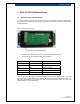
DI-100 User's Guide 1 INTRODUCTION The DI-100 is a 16-Bit Analog-to-Digital Load Cell Interface. It converts millivolt-per-volt rated output of an analog strain-gauge load cell into a USB digital load cell. Attach the load cell wiring to the 5-position terminal block, enter the mV/V setting, plug the DI-100 to an available USB port on your PC, and you’ve got a Windows PC friendly weighing module. Standard Features: • USB Powered. The DI-100 and the load cell are powered entirely by your PC’s USB port.
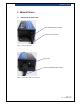
DI-100 User's Guide 2 MODULE DETAILS 2.
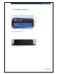
DI-100 User's Guide 2.2 DI-100 Mechanical Dimensions 4.2” 1.6” 3.2” Figure 3: Mechanical Top View 0.
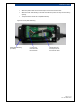
DI-100 User's Guide 3 STEP BY STEP OPERATING GUIDE 3.1 Attach the Load Cell to the DI-100 If you have ordered a load cell with the DI-100, we would have made the load cell attachment to the DI-100 for you. Please skip the following steps and go directly to next section (Install Virtual COM Port Drivers). Figure 5: DI-100 (before assembly) Opening for Strain Relief Bushing • Route the load cell cable through the opening of the strain relief bushing.
DI-100 User's Guide • Attach the plastic base and use the tie-wrap to secure the load cell cable. • Attach the strain relief bushing to the load cell cable and push it securely into the bushing opening. • The picture below shows the completed assembly.
DI-100 User's Guide 3.2 Install Virtual COM Port Drivers The DI-100 may be accessed either through PC’s virtual COM port interface or through the optional LoadVUE program. This document will focus on the virtual COM port interface. Before connecting the DI-100 to your PC, please install the drivers first using the included iLoad Digital USB Driver CD.
DI-100 User's Guide 3.5 DI-100 Initial Setup DI-100 purchased with a load cell If you have purchased a load cell together with the DI-100, we would have performed the calibration at our factory for you. No further setup is required. You may start to use your load cell now: • Type: ? to view the command list. • To tare (i.e.
DI-100 User's Guide 4 CALIBRATING THE DI-100 Please ensure the UNIT and LC (load capacity) commands are entered accordingly, prior to performing the calibration. 4.1 Calibration Mode The DI-100 supports two calibration modes: The mV/V calibration or the 2-Point Linear Calibration. You may perform the calibration for either mode independently and select the actual calibration mode in use. 4.
DI-100 User's Guide 4.3 2-Point Calibration Two-Point Calibration is recommended if calibrated weights are available to perform the calibration. Point 1 is with no load and Point 2 is with load. You could calibrate Point 2 at full load or at the maximum weight range you would be using. • Ensure UNIT and LC commands have been setup prior to starting the calibration. • To select the 2 point calibration mode, type: CAL 2 • Remove all loads, type: 2PCAL xyz .
DI-100 User's Guide 5 DI-100 COMMAND SUMMARY Please note the commands are not case sensitive. All alphabets are converted and stored as uppercase letters, including the ID string name. 5.1.1 UNIT © Function: Set (returns) currently selected units Summary: Sets or returns the unit types: mLB (milli pounds), LB (pounds), KG (kilograms) or N (Newtons) Example: UNIT LB ← (sets units to pounds) UNIT ← (displays currently set units) 5.1.
DI-100 User's Guide 5.1.4 TARE © Function: Tares, or sets the display ZERO value. Summary: When this command is issued, the current A/D converter value is retained as ZERO output value. All subsequently output values are referenced to this value. Example: TARE ← 5.1.5 CAL © Function: Sets (returns) calibration type Summary: Sets or returns the currently selected calibration type. Acceptable parameteres are: m for milliVolt calibration 2 for 2 point calibration Example: 5.1.
DI-100 User's Guide 5.1.8 W© Function: Displays the current weight Summary: Displays the measured weight in the currently selected units Example W← 5.1.9 WC © Function: Continuously outputs current weight Summary: Displays the measured weight continuously. Press key to stop. Example WC ← 5.1.10 R© Function: Return RAW ADC value Summary: Display raw A/D values Example R← 5.1.
DI-100 User's Guide 5.1.12 SETTINGS © Function: Returns all current setting values Summary: Displays all settings stored in the DI-100 non-volatile memory Example SETTINGS ← 5.1.
DI-100 User's Guide 6 DI-100 TECHNICAL SPECIFICATIONS Performance Resolution 16-Bit A/D Update Speed Approx. 7.5 sample per second Rated Input Up to 3mV/V (3mv per volt) Environment Operating Temperature -10 to 55C (15 to 131F) Storage Temperature -20 to 85C (-5 to 185F) Humidity 5 to 85% RH Non Condensing Voltage Powered by USB port Power 5Vdc @ 30mA Vibration Not to exceed 4 mm displacement at 16.