48501 Warm Springs Blvd Suite 109 Fremont, CA 94539 (510) 623-9600 www.loadstarsensors.com DI-1000 High Precision Resistive Load Cell to USB Adapter Users Guide Copyright © 2008, 2014 Loadstar Sensors, Inc.. All rights reserved.
DI-1000 Di1000 User Guide Notes © Copyright 2008/2014 Loadstarsensors Inc. All Rights Reserved. No part of this manual may be reproduced in any form or by any means (including electronic storage and retrieval, or translation into a foreign language) without prior agreement and written consent from Loadstarsensors, Inc. as governed by United States and international copyright laws. Manual Part Number 033-01591 First Edition: November 2008 Fifth Edition: February 2014 Loadstar Sensors Inc.
DI-1000 Di1000 User Guide WARNING 1. Do not use the DI-1000 with the cover, or part of the cover removed or loose, as a hazardous condition may result. Inspect the case for cracks or missing plastic. Do not use if the display is damaged. 2. Use only AC Adapter Charger(s), which conforms to the display required voltage and current ratings provided. 3. Do not operate the display in an explosive atmosphere, or in the presence of flammable gases or fumes. 4.
DI-1000 Di1000 User Guide The Directive aims to reduce the waste arising from electrical and electronic equipment, and improve the environmental performance of everything involved in the life cycle of electrical and electronic equipment. This is translated into the following requirements: * Producers (manufacturers or importers) of electrical and electronic equipment will be required to register in their countries.
DI-1000 Di1000 User Guide Table of contents: 1 2 3 4 5 INTRODUCTION .........................................................................................................................7 1.1 External DI-1000 Connections .............................................................................................8 1.2 DI-1000 Mechanical Dimensions .........................................................................................9 STEP BY STEP OPERATING GUIDE ................................
DI-1000 Di1000 User Guide List of figures: Figure 1: Load cell Wiring Block Connections .................................................................................... 8 Figure 2: Power and Host connections ............................................................................................... 8 Figure 4: Mechanical Long Side View (switch side) .......................................................................... 9 Figure 5: Mechanical End View (Power adapter and host connector) ........
DI-1000 Di1000 User Guide 1 INTRODUCTION The Basic Loadstar Sensors DI-1000U High Precision Load Cell Interface module provides a convenient method to convert nearly any existing millivolt output load cell into a PC friendly USB load cell! Just attach your 4 or 6 wire strain gauge load cell to the convenient 8-pin wiring connector, plug the USB host connector to your PC, and voila! you’ve got a complete Windows PC ready load cell measurement system. The unit can be powered entirely by the PC’s USB port.
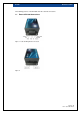
DI-1000 Di1000 User Guide The following pictures of the DI-1000 show the external connections. 1.1 External DI-1000 Connections Figure 1: Load cell Wiring Block Connections Figure 2: Power and Host connections Page: 8 / 25 P/N : 033-01591 Rev.
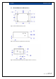
DI-1000 1.2 Di1000 User Guide DI-1000 Mechanical Dimensions Figure 3: DI-1000 Mechanical Top View Figure 4: Mechanical Long Side View (switch side) Figure 5: Mechanical End View (Power adapter and host connector) Page: 9 / 25 P/N : 033-01591 Rev.
DI-1000 Di1000 User Guide Figure 6: Removable Wiring Connector End (Load cell connection) 2 STEP BY STEP OPERATING GUIDE Designed for ease of use, the DI-1000 is easy to bring up. The following steps should get you up and running quickly. 2.1 Plug in the AC power adapter to your DI-1000 2.
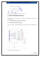
DI-1000 Di1000 User Guide Note that, as shown in the following picture, for a 4-wire load cell, you will need to add an external jumper between pins 1 and 2 (+EXsens and +EX) as well as between pins 5 and 6 (EXsens and –EX). Figure 8: Six Wire Load cell Wiring Schematic We’ve included a handy reference chart below that you can use to help determine how to correctly wire your load cell to the DI-1000 wiring connector. Page: 11 / 25 P/N : 033-01591 Rev.
DI-1000 Di1000 User Guide Table 1: Typical Load Cell Wiring Color Table +Excitation (+EX) -Excitation (-EX) +Signal (+SEN) -Signal (-SEN) Shield (Earth) +Sense (+EXSENS) -Sense (-EXSENS) A&D Engineering Red White Green Blue Yellow (Tie to +EX) (Tie to –EX) Allegany Green Black White Red Bare (Tie to +EX) (Tie to –EX) Beowulf Green Black White Red Bare (Tie to +EX) (Tie to –EX) BLH Green Black White Red Yellow (Tie to +EX) (Tie to –EX) Cardinal Green Black Red Whi
DI-1000 Di1000 User Guide The DI-1000 connects signal ground to the adapter power ground, and also connects to the USB signal power ground. Ideally this ground should be connected to any cable shield, but not the load cell body. Many load cell assemblies connect the cable shield to the load cell body. This creates a problem, since any ground connection between the load cell and your system ground will induce a current in this combined ground system.
DI-1000 Di1000 User Guide 4. Enter the desired amplifier gain: GAIN 64 ← 5. Enter the desired samples/sec: SPS 60← 6. Reset the zero value of the sensor: TARE ← 7. Set the calibration mode to be used for load measurements. You can set mV/V calibration by entering CAL m←. Two point calibration mode is selected by typing CAL 2←. Assuming you have already entered a calibration (see the next section) for the selected mode, you may now monitor the load on the load cell: type WC ← at the terminal window.
DI-1000 Di1000 User Guide 3 CALIBRATING THE DI-1000 Two calibration modes are currently supported by the DI-1000 firmware: 1. Millivolt calibration 2. 2-point linear calibration You may perform the calibration for either mode at any time and independently select the actual calibration mode to be used. Please ensure that the load capacity of your load cell is entered correctly using the LC command before any calibration is performed. 3.
DI-1000 Di1000 User Guide The DI-1000 responds with a number and “Calibration complete!” Your two point calibration has been stored. The number reported represents the mV/V of the load cell as computed by the DI-1000. Page: 16 / 25 P/N : 033-01591 Rev.
DI-1000 Di1000 User Guide 4 ADDITIONAL CONSIDERATIONS 4.1 Effect of Improper Grounding on typical resolution 4.2 Noise (nV) vs Amplifier Gain Figure 9: Typical RMS noise Values (nV) vs. sample rate 4.3 Effect of Sample Rate on typical resolution (bits) Figure 10: Typical noise free equivalent resolution (bits) Page: 17 / 25 P/N : 033-01591 Rev.
DI-1000 Di1000 User Guide 5 DI-1000 COMMAND SUMMARY The commands for the DI-1000 can all be entered without parameters to have the DI-1000 report the value of the appropriate parameters in memory. For example, entering UNIT KG← sets the DI1000 units to KG. Now entering UNIT← gets the DI-1000 to respond with the currently set units, i.e. KG. 5.1.
DI-1000 5.1.4 Di1000 User Guide TARE Function: Tares, or sets the display ZERO value. Summary: When this command is issued, the current ADC value, is retained as the currently defined ZERO output value. All output values are referenced to this value. Example: TARE ← 5.1.5 GAIN Function: Sets (returns) input amplifier gain Summary: Sets (returns) the input amplifier gain. This is used to compensate for different load cell impedances, and re-scaling of device input gain.
DI-1000 5.1.8 Di1000 User Guide mVOLT Function: Sets (returns) the current mV calibration parameter Summary: Sets (returns) the current sensor mV calibration parameter. This may be the parameter listed on the sensor, the manufacturers data sheet, or may have been derived through the calibration procedure. Example: MVOLT 2.123 ← 5.1.9 2PCAL Function: Runs the 2 point calibration procedure Summary: Begins the 2 point calibration procedure.
DI-1000 5.1.12 Di1000 User Guide WU Function: Displays current weight & units Summary: This is similar to the W command except that the unit is also reported by the DI1000. Example WU ← -0.363733 LB 5.1.13 Function: R Return RAW ADC value Summary: Example 5.1.14 Function: R← SETTINGS Returns all current setting values Summary: Example 5.1.15 Function: SETTINGS ← ? Returns the command summary Summary: Example ?← Page: 21 / 25 P/N : 033-01591 Rev.
DI-1000 Di1000 User Guide 6 ZIGBEE WIRELESS VERSION The DI-1000 also ships as a “wireless” version, with an internal battery for true cable free operation. A separate USB “dongle” is provided to plug into the PC, which wirelessly communicates with the remote DI-1000 and attached loadcell device. The wireless link between the DI-1000 and the PC uses a point to point variant of the ZigBee 802.15.
DI-1000 Di1000 User Guide After connecting the DI-1000 a new port should appear: In the above figure, COM22 corresponds to the virtual COM port of the DI-1000 Dongle. Next, open Hyperterminal, and create a new connection corresponding to your attached DI-1000 device: Select the COM port previously determined to correspond to the DI-1000: Set the Baud Rate, parity, data bits, and number of stop Bits, as 9600-N-8-1.
DI-1000 Di1000 User Guide Click Apply, OK and several times. You should get an “A” returned onscreen for every pressed. You many now type ASCII commands to the DI-1000, to remotely monitor and control the attached sensors. You may press “?” at any time to see the available command list. Please continue at section 6.4 Continuation of the Quick Start The quick start process continues the same as in section 3.7 above with the wired version. Please continue there.
DI-1000 Di1000 User Guide 7 DI-1000 TECHNICAL SPECIFICATIONS Performance Resolution See Figure 10: Typical noise free equivalent resolution (bits) Output Resolution Dynamic, Sensor Dependent Update Speed Programmable, 7.