
User's Manual


AT Command Manual v1.3
@2010 LM- Technologies Ltd www.lm-technologies.com Page 11 of 18
2.8.11.1.1 Response
<command_response>
The meaning of the modems signals is described in section 2.8.11.3
2.8.11.2 AT+MODEM?<cr>
2.8.11.2.1 Response
<cr,lf>MODEMc<command_response> if the command is successful. Here, c- current
modem signal setting. E.g on default setup, the response will be <cr,lf>MODEM-
<command_response>
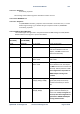
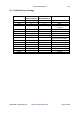
2.8.11.3 Modem Signal Meaning
The modem signal setting is used in conjunction with AT+FLOW Settings to enable/disable
RS232 modem control signals as per the table below.
FLOW CONTROL
(AT+FLOW)
MODEM SIGNAL
(AT+MODEM)
RS232 SIGNALS Description
FLOW- MODEM- Tx, Rx, GND 3 wire configuration
FLOW+ MODEM- Tx, Rx, GND, RTS, CTS
RTS CTS signals are used for data
flow control between host and
adapter, and NOT transferred to
remote side wirelessly.
FLOW- MODEML
Tx, Rx, GND, RTS<->CTS,
DTR<->DSR
RTS looped back to CTS, DTR looped
back to DSR
FLOW+ MODEML
Tx, Rx, GND, RTS, CTS,
DTR<->DSR
RTS CTS signals used for data flow
control between host and adapter,
and NOT transferred to remote side
wirelessly. DTR looped back to DSR.
This configuration is equivalent to
LM048 adapter running v4.5x
firmware
FLOW- MODEMR
Tx, Rx, GND, RTS(R),
CTS(R), DTR(R), DSR(R)
All 7 signals used. All RS232 control
signals (DTR, DSR, RTS and CTS)
transferred wirelessly to remote
side.
FLOW+
MODEMR
Tx, Rx, GND, RTS, CTS,
DTR(R), DSR(R)
All 7 lines used. Only DTR, DSR
signals transferred wirelessly to
remote side. If RTS, CTS signals are
not used, then this configuration is
equivalent to LM048 SPA Adapter
running v4.6X firmware.