
User Manual

5,521,591
13
quickly.
See
Arora,
supra;
and
Leighton,
supra
for
more
details.
Circuit
Switching
The
above
described
routing
method
works
well
for
packet
switching.
It is
not
as
appropriate
for
direct
applica
tion
to
circuit
switching.
Nevertheless,
a
similar
approach
can
be used
for
circuit
switching.
The
circuit~switching
method
adopts
an
approach
similar
to
the
packet
switching
method
but
additionally
makes
use
of
the
dispersion
prop
erty
of
the
logical
clusters.
In
order
for
the
circuit-switching
algorithm
to
succeed,
the
multibutter?y
network
must
be
lightly
loaded
by
some
?xed
constant
factor Z.
Thus,
in
an
N-row
multibutter?y
network,
connections
are
made
only
between
the
N/Z
inputs
and
outputs
in
rows
that
are
multiples
of
Z.
Since
the
other
inputs
and
outputs
are
not
used, the
?rst
and
last
1
gZ
levels
of
the
network
can
be
removed,
and
the
N/Z
inputs
and
outputs
can
each
be
connected
directly
to
their
Z
descen
dants
and
ancestors
on
levels
1
g2
and
lgN-l
gZ,
respec
tively.
It is
relatively
easy
to
extend
paths
from
one
level
to
the
next
in
a
multibutter?y
with
the
(ot,5)
dispersion
property.
The
reason
is
that
those
paths
at
switches
with
unique
neighbors
can
be
trivially
extended
without
worrying
about
blocking
any
other
path
trying
to
reach
the
next
level.
By
proceeding
recursively,
it
is
easy
to
see
that
all
the
paths
can
be
extended
from
level
L
to
level
L+l
(for
any
L)
in
log(N/Z2L)/log(1/L-5)
steps.
When
such
a recursive
approach
is
adopted,
the
method
proceeds
in
steps
wherein
each
“step”
of
a switch
node
making
a
local
routing
decision
consists
of
(see
?owchart
in
FIG.
16):
l.
sending
out a
“proposal”
for
every
path
still
waiting
to
be
extended
to
the
output
(level
L+1)
neighbors
in
the
desired
direction
(up
or
down)
(Step
106);
2.
sending
back
acceptance
of
the
proposal
from
every
output
node
that
receives
precisely
one
proposal
(Step
108).
If
more
than
one
proposal
is
received,
none
are
accepted;
3.
advancing
every
path
receiving
an
acceptance
to
one
of
its
accepting
outputs
on
level
L+l
(Step
110).
Splitters
connecting
level
L
to
level
L+1
have
M=Nl2L
inputs.
At most
M/Z
paths
can
pass
through
splitters
con
necting
level
L
and
level
L+l
by
de?nition
of
Z.
Since
Z>l/ot,
the
set
of
switches
containing
paths
needing
to
be
extended
has
a
size
of
at
most
otM.
The
(m5)
dispersion
property
can
be
applied
to
ensure
that
at
each
step,
the
number
of
paths
still
remaining
to
be
extended
decreases
by
a
(l—6)
factor.
Hence,
all
of
the
paths
are
extended
in
log(N/Z2L)/log(l/(1—5))
steps,
as
claimed.
By
using
the
path
extension
algorithm
just
described
on
each
level
in
sequence,
all
of
the
paths
can
be
constructed
in
MEL
logzi
I
N-I
1
I
21-20
*L
g
+
zouogzN)
-
log
1__6
2logl_z,3
bit-steps.
To
construct
the
paths
in
O(logN)
bit~steps
the
algorithm
may
be
modi?ed.
Speci?cally,
given
a
fraction
<ot
of
paths
that
need
to
be
extended
at
an
M-input
splitter,
the
method
does
not
wait
O(logM)
time
for
every
path
to
be
extended
before
it
begins
the
extension
at
the
next
level.
Instead,
it
waits
only
0(1)
steps,
in
which
time
the
number
of
unextended
paths
falls
to
a
fraction
p
of
its
original
value,
where
p<l/d.
Now
the
path
extension
process
can
start
at
the
15
25
35
40
45
50
55
65
14
next
level.
The
danger
here
is
that
the
p
fraction
of
paths
left
behind
may
?nd
themselves
blocked
by
the
time
they
reach
the
next
level,
and
so
it
is
necessary
to
ensure
that
this
will
not
happen.
Therefore,
stalled
paths
send
out
place-holders
to
all
of
their
neighbors
at
the
next
level,
and
henceforth
the
neighbors
with
place-holders
participate
in
path
extension
at
the
next
level as
if
the
place-holders
were
paths.
Of
course,
the
neighbors
holding
place-holders
must
in
general
extend
in
both
the
upper
and
the
lower
output
portions
of
the
splitter,
since
they
do
not
know
yet
which
path
will
ulti
mately
use
them.
It
is
worth
noting
that
a
place-holder
not
only
reserves
a
spot
that
may
be
used by
a path
at
a
future
time,
but
also
helps
to
chart
out
the
path
by
continuing
to
extend
ahead.
In
order
to
prevent
place-holders
from
multiplying
too
rapidly
and
clogging
the
system
(since
if
the
fraction
of
inputs
of a
splitter
which
are
trying
to
extend
rises
above
ot,
the
path
extension
algorithm
may
cease
to
work),
it
is
necessary
to
ensure
that
as
stalled
paths
get
extended,
they
send
cancel
lation
signals
to
the
place-holder
nodes
ahead
of
them
to
indicate
that
the
place-holder
nodes
are
no
longer
needed.
When
a
place-holder
node
receives
cancellation
signals
from
all
the
nodes
for
which
the
place-holder
node
was
holding
a
place,
the
place-holder
node
is
removed
and
ceases
to
extend
anymore.
In
addition,
the
place-holder
nodes
send
cancel
lations to
any nodes ahead
of
them
that
may
be
holding a
place
for
them.
The
O(logN)-step
algorithm
for
routing
paths
proceeds
in
phases
consisting
of
the
following
two
types
of
steps:
1.
Steps
of
passing
cancellation
signals.
There
are
C
such
steps.
The
cancellation
signals
travel
at
the
rate
of
one
level
per
step;
2.
Steps
of
extending
from
one
level
to
the
next.
There
are
T
such
steps.
In
this
time, the
number
of
stalled
(i.e.,
unextended)
paths
at
each
splitter
drops
by
at
least
a
factor
of
p,
where
P§(l——5)T.
Each
path
is
restricted
to
extend
forward
by
at
most
one
level
during
each
phase.
The
?rst
wave
of
paths
and
place
holders
to
arrive
at
a
level
is
referred
to
as
the
wavefront.
The
wavefront
moves
forward
by
one
level
during
each
phase.
If
a
path
or
a
place-holder
in
the
wavefront
is
not
extended
in
T
steps,
it
sends
place-holders
to
all
of
its
neighbors
at
the
end
of
the
phase.
It
is
assumed
that
C22
so
that
cancellation
signals
have
a
chance
to
catch
up
with
the
wavefront.
It is
also
assumed
that
dZ3.
(See
Arora,
supra
for
more
details
and
a
proof
that
the
algorithm
quickly
estab
lishes
all
paths).
N
onblocking
Networks
The
preceding
method
works
well
for
static
message
routing
problems
(i.e.,
for
problems
in
which
the
messages
to
be
routed
all
start
at
the
input
ports
of
the
circuit
at
the
same
time).
In
some
applications,
however,
such
as
tele
phone
networks,
the
messages
to
be
routed
arrive
at
the
input
ports
at
di?cerent
times. In
such
cases,
it
is
desirable
to
route
the
messages
in
a
nonblocking
manner.
The
goal
of such
routing
switches
is
to
interconnect
the
terminals
and
switches
so
that
any
unused
input-output
pair
can
be
con
nected
by
a path of
unused
switches, regardless
of
the
other
paths
that
exist
at
the
time.
Such
a
network
is
said
to
be
nonblocking.
Nonblocking
in
this
strong
sense
is
to
be
distinguished
from
the
rearrangeable
properties
of
Benes
networks
which
allow
further
connections
but
require
rerouting
of
existing
connections.
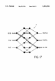
The
6-terrninal
graph
41
shown
in
FIG.
17
is
nonblocking
since
no
matter
which
input-output
pairs
are
connected
by
a
path,
there
is
a