
User Manual

5,521,591
11
of an
input
switch
in
a
logical
cluster
is
“available”
if
all
of
the
following
conditions
are
met:
1.
the
switch
is
not
faulty;
2.
the
switch
is
not
busy;
and
3.
the
switch
is
connected
to
at
least
6
available
output
ports
in
each
output
group,
where
5
is
a
prespeci?ed
threshold
value
that
is
at
least
one.
Otherwise,
the
switch
is
said
to
be
“unavailable”.
By
only
sending
messages
to
“available”
switches,
the
routing
meth
ods
are
able
to
avoid
switches
on
multibutter?ies
that
are
faulty
or
busy.
Such
an approach
also
avoids
the
routing
of
a
message
into
a
position
wherein
the
message
might
only
be
further
routed
to
a
faulty
or
busy
switch.
Packet
Switching
It
is
possible
to
run
a
variety
of
package
switching
methods,
e.g.,
a
greedy
algorithm.
Following
is
a
preferred
greedy
algorithm. In
describing
the
preferred
packet
switch
ing
method,
it
is
assumed
unless
stated
otherwise
that
the
multibutter?y
networks
being
used
have
expansion
property
(ot,B)
for
2ot<l
and
[i>l.
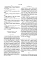
A
?owchart
outlining the
major
steps
of
the
packet switching
method
is
shown
in
FIG.
12.
Initially,
packets
to
be
routed
across
the
switching
network
are
partitioned
into
waves
(Step
50)
so
that
at
most
one
packet
in
each
wave
is
destined
for
any
set
of
Z
contiguous
outputs.
One
way
to
achieve
such
a
partitioning
into
waves
is
to
group
packets
into
the
same
wave
if
they
are
in
the
same
permutation
and
their
destinations
are
congruent
modulo
Z.
For
P
permutations
to
be
routed,
this
approach
of
partition
ing
results
in
at
most
PL
waves.
In
general,
Z
should
be
set
to
equal
l/(20t),
since
then
it
is
certain
that
at
most
M1(2Z)=
otM
packets
in
any
wave
pass
through
the
up
(or
down)
edges
of
any
M-input
splitter
of
the
multibutter?y
(for
any
M).
This
allows
the
(ot,[3)
expansion
property
to
apply
to
the
set
of
inputs
of
any
splitter
occupied
by
the
packets
of
a
single
wave
at
any
time.
(E.
g.,
if
k
inputs
of
a
splitter
contain
packets
of a
single
wave
that
want
to
traverse
up
edges,
then
these
inputs
are
connected
to
at
least
Bk up
outputs.)
This
is
because
packets
going
through
the
M12
up
(or
M12
down)
splitter
outputs
can
only
be
destined
for
the
descendant
set
of
M12
contiguous
multibutter?y
outputs.
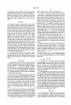
The
routing
of
the
packets
proceeds
in
stages
(see
Steps
52
and
54),
wherein
each
stage
consists
of
an
even
phase
(Step
56)
and
an
odd
phase
(Step
58),
and
each
phase
consists
of
2d
steps.
In
even
phases,
packets
are
sent
from
even
levels
to
the
next
odd
levels
(Step
56),
and
in
odd
phases,
packets
are
sent
from
the
odd
levels
to
the
next
even
levels
(Step
58).
The
edges
connecting
levels
are
colored
in
2d
colors
so
that
each
node
is
incident
to
one
edge
of
each
color.
In
each
phase,
the
edges
are
processed
by
color
in
sequence
for
all
colors
such
that
one
step
is
dedicated
per
color.
A
?owchart
of
the
activity
performed
in
a
step
is
provided
in
FIG.
13.
For
each
step (see
Step
62),
a
packet
is
moved
forward
along
an
edge
with
the
color
being
moved
during
the
step
(Step
68)
provided
that
there
is
a
packet
in
the
switch
at
the
tail
of
the
edge
that
wants
to
go
in
that
direction
(up
or
down)
(Step
64)
and
further
provided
that
there
is
no
packet
in
the
switch
at
the
head
of
the
edge
(Step
66).
Alternatively,
if
there
is
a
packet
in
the
switch
at
the
head
of
the
edge
(Step
66)
and
if
the
packet
is
in
a
later
wave
than
the
packet
at
the
tail
of
the
edge
(Step
70),
the
two
packets
are
swapped
(Step
72)
so
that
the
packet
in
the
earlier
wave
moves
forward.
Other
wise,
the
packet
is
not
moved
(Step
74).
Note
that
every
switch
processes and/or
contains
at
most
one
packet
at
any
step.
10
15
20
25
35
40
45
50
55
65
12
If
there
is
only
one
permutation
to
route,
then
each
input
I
of
the
multibutter?y
starts
with
one
packet.
If
there
are
P
permutations
to
be
routed,
however,
it
is
useful
to
augment
the
front-end
of
the
multibutter?y
with
P-l
levels
of
(1
(random)
matchings
so
that
the
queue
size
of
l
at
the
input
level
can
be
preserved.
The
augmentation
requires
no
more
hardware
than
that
necessary
to
augment
the
front
end
of
each
component
butter?y
with
a
P—l
cell
linear
array.
Moreover,
the
augmentation
ensures
that
the
preprocessing
levels
have
an
(ot,B)-expansion
property
at
least
as
strong
as
the
?rst
level.
For
notational
purposes,
these
additional
levels
will
be
referred
to
hereinafter
as
levels
—1,
—2,
. .
.
,
-—(P—1).
The
waves,
edge
coloring,
and
odd-even
phases
can
be
dispersed
for
most
applications.
Speci?cally,
each
packet
is
forwarded
unless
all
queues ahead
of
it
exceed
some
pre
speci?ed
threshold
of
fullness.
This
approach
is
denoted
as
the
greedy
algorithm.
For
more
details
on
the
greedy
algo~
rithm,
see Arora,
supra;
and
Leighton,
supra.
Fault
Tolerance
The
present
invention
also
embodies
a
method
for
fault
tolerance
in
networks
such
as
the
multibutter?y.
The
central
idea
of
the
method
is
to
identify
and
remove
those
parts
of
the
network
that
contain
too
many
faulty
switches
to
be
used.
The
goal
of
this
recon?guration
process
is
to
salvage
as
much
of
the
working
hardware
as
possible
while
leaving
largely
intact
the
expansion
property
of
the
network.
Once
an
appropriate
set
of
inputs
and
outputs
have been
removed,
the
greedy
algorithm
described
in
the
previous
section
can
be
applied
to
route
packets
between
the
remaining
inputs
and
outputs.
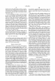
The
?rst
step
in
the
fault
tolerance
method
is
to
specify
the
outputs
to
remove.
A
?owchart
of
the
output
removal
scheme
is
given
in
FIG.
14.
In
particular,
each
splitter
in
the
multibutter?y
is
examined
(Steps
80
and
82).
If
more
than
an
e0
fraction
of
the
input
switches
are
faulty
(Step
84),
where
e0=2ot([5'—1)
and
B'=[5—(d12),
then
the
splitter
is
“erased”
from
the
network
(Step
86).
In
addition
all
of
its
descendant
switches
and
outputs
are
likewise
“erased”
(Step
86).
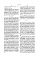
The
fault
tolerance
method
next involves
determining
which
inputs
to
remove
(see
?owchart
in
FIG.
15).
The
?rst
step
(87)
in
the
process
is
to
declare
any
faulty
switch
as
unavailable.
Working
from
the
(lgN)th
output
level
back
wards
(see
Steps
89,
90,
100,
and
102),
each
switch
is
examined
(Box
90)
to
determine
if
at
least
half
of
its
upper
outputs
lead
to
faulty
unavailable
that
have
not
been
erased
(Step
92),
or
if
at
least
half
of
its
lower
outputs
lead
to
unavailable
switches
that
have
not
been
erased
(Step
94).
If
so,
the
switch
is
declared
(Step
96)
to
be
unavailable.
(But
it
is
not
erased.
Where
outputs
lead
to
erased
switches,
they
need
not
be
declared
unavailable
in
subsequent
checking
of
preceding
levels
because
the
outputs
from
the
erased
switches
are
invalid).
This
process
is
repeated
for
all
switches
on
a
level
(see
Step
98)
and
for
each
level
(Steps
98
and
100)
until
all
levels
have
been
examined
(Step
102).
All
the
remaining
unavailable
switches
are
erased
(Step
104).
What
is
left
is
a
network
in
which
every
input
in
every
splitter
is
linked
to
d12
functioning
upper
outputs
(if
the
descendant
multibutter?y
outputs
exist)
and
d12
functioning
lower
outputs
(if
the
corresponding
multibutter?y
outputs
exist).
Hence,
every
splitter
has
an
(ot,[3')
expansion
prop
erty.
Thus,
it
can
be
proven
that
the
greedy
algorithm
still
routes
any
permutation
on
the
remaining
inputs
and
outputs