
User Manual

5,521,591
5
FIG.
5
is
an
illustration
of a
butter?y
switching
network.
FIG.
6
depicts
the
blocks of
a
butter?y
network
and
a
sample
routing
path.
FIG.
7
depicts
an
example
of a
fat
tree.
FIG.
8
shows
two
butter?y
networks
and
the
twin
butter
?y
they
form
when
merged.
FIG.
9
shows
an
example
twin
multibutter?y
switching
network.
FIG.
10
shows
an
example
2-multi-Benes
switching
net
work.
FIG.
11
is
an
illustration
of
a
splitter
having
more
than
two
levels.
FIG.
12
is
a
?owchart
of
the
major
steps
of
the
packet
switching
method
of
the
present
invention.
FIG.
13
is
a
?owchart
of
the
edge
coloring
scheme
employed
in
a
packet
switching
method
of
the
present
invention.
FIG.
14
is
a
?owchart
of a
method
for
striking
faulty
input
splitters
in
a
switching
network
to
boost
fault
tolerance
of
the
switching
network.
FIG.
15
is
a
?owchart
illustrating
a
method
for
removing
faulty
switches
in
a
switching
network
to
increase
fault
tolerance.
FIG.
16
is
a
?owchart
of
the
major
steps
of a
circuit
switching
algorithm.
FIG.
17
depicts
a
non-blocking
network.
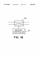
FIG.
18
shows
a
2X2
switch
having
a
routing
controller
for
controlling
operation
of
the
switch
to
perform
the
processes
of
FIGS.
12-16.
DETAILED
DESCRIPTION
OF
THE
PREFERRED
EMBODIMENT
Logical
Clusters
The
basic
building
block
of
many
switching
networks
is
the
logical
cluster.
A
logical
cluster
is
a
group
of
switches
and
wires
that
perform
a
high
level
task.
Examples
of
logical
clusters
are
splitters,
mergers
and
condensers.
The
splitter
10
shown
in
FIG.
2
splits
a
set
of
inputs
into
two
sets
of
outputs.
Speci?cally,
the
splitter
10
has a
set
of
inputs
4
that
lead
into
a
set
of
2X2
switches
11
that
constitute
an
input
block
5.
Wires
9
connect
the
input
block
5
of
switches
to
the
output
blocks
7a
and
7b
of
switches
11.
The
outputs
of
these
switches 11
are the
two
sets
of
outputs
of
the
splitter
10.
Each
switch
11
in
the
input
block
5
is
connected
to
at
least
one
output switch
11
in
each
of
the
output
blocks
7a
and
7b.
The
splitter
10
serves
to
route
the
input
4
to
the
appropriate
output
block
7a
and
7b.
It
does
not
matter
which
splitter
output
6
a
message
is
routed
as
long
as
each
message
is
routed
to
a
splitter
output
6
in
the
correct
output
block
7a,
7b.
Another
common
variety
of
logical
cluster
is
the
merger
21
(FIG.
3).
The
merger 21
is
comprised
of
multiple
input
blocks
such
as
12a and
12b
shown
in
FIG.
3.
In the
merger
21 shown,
the
input
blocks
12a
and 12b
lead
via
wires
9
into
a
single
output
block
13.
Thus,
the
different
sets
of
inputs
feeding
into
the respective
input
blocks
12a
and 12b
are
merged
into
a
single
set
of
outputs
from
output
block
13.
A
third
logical
cluster
that
is
used
in
switching
networks
is
the
condenser
23
(FIG.
4).
It
condenses
a
set
of
inputs
into
a
lesser
number
of
outputs.
15
25
35
40
45
SO
55
65
6
Butter?y
Networks
A
butter?y
network
is
a
common
example
of a
switching
network.
It
is
referred
to
as
a
butter?y
network
because
the
connections
between
nodes
form
a
pattern
resembling
a
butter?y.
A
butter?y
network
has
the
same
number
of
inputs
as
it
has
outputs.
The
inputs
are
connected
to
the
outputs
via
a
set
of
switches
organized
into
successive
levels
of
switches.
An
N-input,
N-output
butter?y
network
has
log2N+l
(hereinafter
log2
will
be
referred
to
as
1
g) levels
of
switches,
each
level
having
N
2x2
switches.
For
a
message
to travel
from
input
to
output,
it
must
traverse
at
least
one
switch
in
each
successive
level.
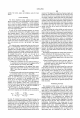
An
example
butter?y
network
8
is
shown
in
FIG.
5.
Each
switch
3
in
the
butter?y
8
has a
distinct
reference
label
<L,r>,
where
L
is
its
level,
and
r
is its
row.
In
an
N-input
butter?y, the
level
L
is
an
integer
between
0
and
lgN,
and
the
row
r
is
a
lgN-bit
binary
number.
The
inputs
and
outputs
reside
on
levels
0
and
lgN,
respectively.
For
L<lgN,
a
switch
labeled <L,r>is
connected
to
switches
<L+1,r>and
<L+l,
r(L)>,
where
r“)
denotes
r
with
the
Lth
bit
complemented.
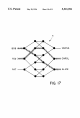
Butter?y
networks
are
composed
of
sequences
of
split
ters.
The
switches
on
each
level
of
a
butter?y
network
are
partitioned
into
blocks
according
to
which
outputs
they
can
reach.
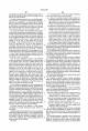
Another
example
butter?y
network
19
is
shown
in
FIG.
6.
The
?rst
level
of
the
butter?y
network
19 can
be
viewed
as
a
single
block
7,
since
all
of
the
inputs
of
the
block
37
can
reach
all
of
the
outputs
of
the
block
37.
The
second
level
has
two
blocks:
one
block
14a
consisting
of
those
switches
that
can
reach
outputs
whose
labels
start
with
0,
and
the
other
block
14b (shown
in
phantom
form)
consisting
of
those
outputs
whose
labels
start
with
1.
Each
block
37,
14a, 14b,
is
the
input
group
of a
subsequent
splitter
having
two
output
groups.
Other
sample
blocks
for the
higher
levels
include
blocks
15a-15d
and
17a-17h.
Any
pair
consisting
of
an
input
and
output
of
the
butter?y
is
connected
by
a
single
logical
(up-down)
path
through
the
butter?y.
An
example
of
such
a
logical
path
through
a
butter?y
network
is
shown
by
the
solid
lines
29
in
FIG.
4,
indicating
the
decreasing
number
of
switches
that
a
message
may
choose
from
in
the
succes
sive
output
blocks
of
the
butter?y.
Fat-Tree
A
fat-tree
is
another
common
example
of a
switching
network
that
is
made
of
splitters
and
mergers.
A
fat~tree
network
16
is
shown
in
FIG.
7.
Its
underlying
structure
is
a
complete
4-ary
tree
(i.e.,
every
vertex
has
four
wires
leading
to
the
next
level
of
the
tree).
Each
edge
in
the
4-ary
tree
corresponds
to
a
pair
of
oppositely
directed
groups
of
wires
called
channels.
The
channel
directed
from
the
leaves
18
to
the
root
20
is
called
an
up
channel;
the
other
channel
is
called
a
down
channel.
A
group
of
up
channels
connecting
four
children
to
their
parent
forms
a
merger,
while
a
group
of
down
channels
connecting
a
parent
to
its
four
children
forms a
splitter.
A
message
routes
up
through
the
mergers
until
it
can
move
down
through
the
splitters
to
its
destina
tion.
The
capacity
of
a
channel
is
the
number
of
wires
in
the
channel.
The
tree
is
referred
to
as “fat”
because
the
capaci
ties
of
the
channels
grow
by
a
factor
of
2
at
every
level.
A
fat-tree
of
height
m
has
M2=22m
leaves
and
M=2’"
vertices
at
the
root.
Degree
A
logical
cluster
of
a
switching
networks
is
said
to
be
low-degree
if
the
degree
of
the
switches
in
the
logical cluster
is
a
small
?xed
constant
(e.g.,
4,
8,
or
16)
that
is
independent