
User Manual

5,521,591
3
group
of
the
second
set
of
switches
that
are
connected
to
precisely
one
of
the
k
switches
in
the
?rst
set
of
switches,
where
kéotN,
and
N
and
k
are
positive
integers.
Both
such
logical
clusters
are
ideal
for
use
in
multibutter?y
switching
networks
and
multi-Benes
switching
networks.
5
and
or
are
positive
constants
less
than
one.
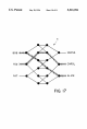
The
present
invention
also
embodies
a
multibutter?y
switching
network
made
from
the
merger
of
individual
butter?y
switching
networks.
For
purposes of
referencing
the
butter?y
switching
networks
it
is
helpful
to
number
them
1
through
d,
where
dis
an
integer.
Each
butter?y
switching
network
has
N
input
switches,
and
it
is
made
of
levels
and
rows
of
switches.
The
butter?y
switching
networks
are
merged
such
that
given
a
set
of
permutations
{111,
.
. .
,
Tim-1)}
where
l'l"=<1tok,
1:1",
. . .
,
1:1
nk>
and
nLk:{[0,
N/2L—1]——>[0,
N/2L—l],
a
switch
in
row
jNI2L+i
of
level
L
of
butter?y
switching
network
k
is
merged
with
a
switch
row
jN/2L+1cL"(i).
Similarly
the
present
invention
embodies
a
multi-Benes
switching
network
that
is
formed
in
a
manner
similar
to
that
of
the
multibutter?y
switching
network. In
particular,
it
is
formed from
d
individual
Benes
switching
networks
num
bered
1
through
d.
The
merger
can
be
described
using
a
set
of
permutations.
Speci?cally,
given
a
set
of
permutations
{111,
. . .
,
TIM-n}
where
l'I",=<n0’,
n1",
. . .
,
7t2lgnk<
and
where
Inf:
[0,
N/2lg""L—l]—9[O,
N/2'g""“—1]
for
OéLélgn
a
switch
in
row
jN/2’g"“L+i
of
level
L
of
Benes
switching
network
number k
is
merged
with
a
switch
in
row
jN/2lg"_
L+TCLk(l)
of
level
L
of
Benes
switching
network
number
k+1
for
all
1§k§(d—1),
all
0§i§N/2’g""L—1,
all
0§j§2'g"_"
—1,
and
all
0-_<-L_5_lgn.
Moreover
for
lgNéLéZlgn,
TELkZ
[0,
N/2L_'g"—1]—>[0,
N/2L“'g"—l],
a
switch
in
row
j
N/2L_’g"+i
of
level
L
of
Benes
switching
network
number
k
is
merged
with
a switch
in
row
jN/2L—'g’l
+1tLk(i)
for
all
1§k§(d—l),
all
0§i§N/2”lg”—1,
all
O§j§2"’g"—1.
Examples
of
these
switching
networks
(i.e.
multibutter?y
switching
networks
and
multi-Benes
switching
networks)
are
where
d=2,
implying
a
twin
multibutter?y
or
a 2-multi
Benes.
Often
times
in
the
prior
art
it
is
common
to
select
the
permutations
II
so
that
they
are
an
identity
map.
In
other
words,
i=1l:(i).
This
choice
of
H
creates
a
dilated
butter?y
switching
network
or
a
dilated
Benes
switching
network.
Such
networks
as
the
multibutter?y
switching
network
and
the
multi-Benes
switching
network
may
be
used
to
produce
a
very
fault
tolerant
routing
scheme.
In
particular,
according
to
the
present
invention
the
output
connections
of
each
switch
in
a
switching
network
organized
into
levels
of
switches
are
examined
to
determine
whether
the
switch
is
available.
The
switch
is
declared
unavailable
if
the
exam
ining
step
reveals
that
the
switch
is
faulty
or
busy,
i.e.,
unusable,
or
does
not
have
a
sufficient
quantity
of
connec
tions
to
available
switches
in
each
output
group
for
each
logical
cluster
of
the
switching
network.
Such
unavailable
switches
are
avoided
in
routing
messages
across
the
switch
ing
networks.
To
further
boost
fault
tolerance,
it
preferred
that
the
input
switches
of each
logical cluster
also
be
inspected
to
determine
how
many
of
the
input
switches
are
faulty.
Where
a
number
of
input
switches
of
a
logical cluster
that
are
faulty
exceeds
a
predetermined
threshold
all
of
the
switches
in
a
logical
cluster
are
declared
faulty
as
well
as
any
descendant
switches
of
the
logical
cluster.
Optimally
this
additional
examining
step
proceeds
from
the log2
Nth
level
of
switches
backwards
towards
the
0
level
of
switches.
In
general,
the
fault
tolerance
approach
may
be expanded
to
heighten
the
integrity
of
routing
of
messages
in
a
switching
network.
In
accordance
with
this
generalized
method
all
switches
are
initially
declared
as
available.
If
a
switch
is
10
25
30
35
45
55
60
65
4
faulty,
busy
or
connected
to
an
insu?icient
number
of
properly
operating
switches
it
is
declared
unavailable.
Mes
sages
are
routed
exclusively
over
available switches.
The
present
invention
encompasses
packet
switching
routing
strategies
as
well
as
circuit
switching
routing
strat
egies.
In
accordance
with
the
packet
switching
method
of
the
present
invention,
packets
of
information
are
routed
across
a
switching
network
comprised
of
several
levels
of
switches
by
?rst
dividing
packets
of information
into
waves.
Once
the
packets
are
divided
into
waves,
the
waves
are
sent
from
even
levels
of
switches
to
odd
levels
of
switches
during
a
?rst
time
frame. In
a
second
time
frame,
the
waves
of
packets
are
sent
from
odd
levels
of
switches
to
even
levels
of
switches.
In
addition,
it
is
preferred
that
colors
are
assigned
to
wires
so
that
each
switch
is
incident
to
one
wire
of each
color.
The
colors
have
a
prede?ned
hierarchy.
During
either
of
the
above
sending
steps,
the
packet
are
sent
sequentially
over
the
wires
to
interconnect
the
switches
according
to
the
color
of
the
wires
in
the
color
hierarchy.
In
general,
a
packet
moves
along
a wire
of
a
given
color
during a
time
frame
if
the
packet
seeks
to
move
to
a
destination
switch
to
which
the
wire
is
connected
and
if
no
other
packet
currently
resides
at
the
destination
switch.
However,
if
during a
sending
switch
step,
a packet
seeks
to
move
along
a
wire
from
a
source switch
to
a
destination
switch
and
another
packet
from
a
later
initiated
wave
currently
resides
at
the
destination
switch,
the
position
of
the
packets
is
swapped
so
that
the
packet
previously
at
the
source
is
at
the
destination
and
vice
versa.
If,
instead,
a
circuit
switching
strategy
is
desired,
the
present
invention
provides
means
for
extending
paths
in
a
circuit
switching
network.
According
to
this
method,
a
proposal
is
sent
from
a
current
node
position
in
the
network.
For
each
message
path
that
seeks
extension, the
proposal
is
sent
to
each
neighbor
node
in
a
desired
direction
of
exten
sion.
Subsequent
to
the
sending
of
a
proposal,
an
acceptance
is
returned
to
the
current
node
position
from
a
neighbor
node
if
the
neighbor
receives
exactly
one
proposal.
Upon
accep
tance,
each
message
path
is
advanced
to
include
an
accept
ing
neighbor
node
if
it
has
one.
To
further
enhance
this
method
of extending
message
paths,
the
additional
step
of
extending
place-holders
may
be
utilized.
The
place-holders
are
sent
on
behalf of
any
message
paths
that
are
not
moved
forward
during a
given
advancing
step.
The
place-holders
serve
to
reserve
a
place
at
a
switch
to
which
the
message
path
seeks
to
extend.
Thus,
as
the
name
implies
the
place-holders
hold
a
place
for
a
stalled
message
path.
Additionally,
it
is
preferred
that
cancellation
signals
are
sent
from message
path
to
place-holders
when
the
place-holders
are
no
longer needed.
The
cancellation
signals
result
in
the
removal
of
the
place-holders
when
the
signals
are
received.
This
prevents
undue
congestion
within
the
switching
network.
It
should
be
noted
that
the
place
holders
are
advanced
as
if
they
are
a
message
path.
Further,
when
a
place-holder
receives
cancellation
signals
from
all
message
paths
for
which
it
is
holding
a
place,
the
place
holder
sends
a
cancellation
signal
to
additional
place-holders
that
are
reserves
a
spot
for
the
place-holder.
BRIEF
DESCRIPTION
OF
THE
DRAWINGS
FIG.
1
depicts
a
2x2
switch.
FIG.
2 shows
a
splitter
logical
cluster.
FIG.
3
illustrates
a
merger
logical
cluster.
FIG.
4
shows
a
condenser
logical
cluster.