
Installation Sheet

ASSEMBLING & INSTALLATION INSTRUCTIONS
The drawing shown may not exactly match the product enclosed.
However, the installation instructions do apply to this product.
58069 52159 45848 45849 45798 45799
WARNING! SHUT POWER OFF AT FUSE OR CIRCUIT BREAKER.
ATTENTION! COUPER LE COURANT AU FUSIBLE OU UN DISJONCTEUR.
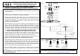
ASSEMBLING THE FIXTURE (Fig.1)
1. Shut off the power at the circuit breaker box. Remove old fixture and all hardware
from Junction Box.
2. Carefully unpack your new fixture and lay out all the parts on a clear area. Take
care not to lose any small parts necessary for installation.
3. Thread the two mounting screws about 1/4” into the pre-drilled holes in the
mounting plate spaced the same distance apart as the holes in the canopy (B).
Attach the mounting plate to the Junction Box with the two Junction Box Screws
as shown. The side of the mounting plate marked "GND" must face out.
The
junction box is not included.
4. Attach the tube(F) to the top center coupling of the lamp holder(G), turn it until
tighten. Raise the pipe thread(D) to the top coupling of the shade(E), turn it until
tighten,
Using the same method install the others pipe. Raise the canopy(B)
onto the end of pipes, aligning the mounting holes, lock it securely with the
lock washer and hex nut(A). Now, catch the
lamp holder’s wires, then through
the shade’s center hole and canopy’s center hole, by turning it clockwise until
tight. NOTE: THE SHADE(E) OF THE PRODUCT MAY VARY.
5. Thread the pipe(H) into the bottom center coupling of the lamp holder and lock it
securely with the hex nut. Raise the steel shim (I), acrylic plate(J) and steel
shim(K) to the bottom of the shade (E), lock it securely with the finial (L).
6. Install the light bulbs(not included) in accordance with the fixture specifications.
NOTE: DO NOT EXCEED THE SPECIFIED WATTAGE!
7. While holding the shade assembly towards the ceiling, connect the electrical wires
as Shown in Fig.2, making sure that all wire nuts are secured. You may have to
wrap the connections with electrical tape. If your outlet has a ground wire (green
or bare copper), connect the fixture ground wire to it. Otherwise connect fixture’s
ground wire directly to the mounting plate with the green screw provided. After
wires are connected, tuck them carefully inside the Junction Box.
8. Raise the shade assembly onto the junction box, aligning screws on mounting
plate with mounting holes in canopy (B) and lock it securely with the column nut
(C).
Your installation is now complete. Return power to the junction
box and test the fixture.
Junction Box
(Not included)
Mounting screw
Green
Screw
(GND)
Junction Box
(Screw)
A
B
C
D
E
F
G
H
I
J
K
L
FIXTURE
WIRES
Black or
Smooth
HOUSE
WIRES
Black(Hot)
FIXTURE
WIRES
White or
Ribbed
FIXTURE
WIRES
Bare
Copper
(Ground)
HOUSE
WIRES
White
(Neutral)
HOUSE
WIRES
Green or Bare
Copper(Ground)
`
Thank you for purchasing a LIVEX product.
Need assistance with parts or assembly? Please call customer service at: 800-761-8056
Or visit us on-line at: WWW.LIVEXLIGHTING.COM
©COPYRIGHT ALL RIGHTS RESERVED.LIVEX LIGHTING,INC. DOC20191058069
FIG.2
FIG.1