
Data Sheet
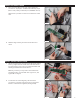
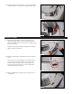

9. Reattach the three wire connectors to the Circuit
Board.
Each connector is keyed (there is a top and bottom),
so it will only fit on the header one way (see Figure 9).
If you feel resistance, turn it over and try again.
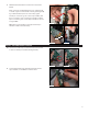
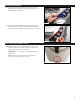
The 4-pin connector goes on the 4-pin header, the
6-pin connector goes on the 6-pin header, and the
8-pin connector goes on the 8-pin header as shown
in Figure 10a.
Note: The 4-pin header to the right of the 8-pin
header is used in the next step.
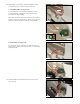
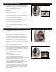
11. Connect the other end of the wire harness to the
4-pin header on the WebConnect module.
3
10. On the Circuit Board, connect the new wire harness
to the unused 4-pin header (see Figure 11a).
Figure 10a
Figure 10b
4-pin
6-pin
8-pin
Figure 9
Key
Figure 12
Figure 11a
Figure 11b
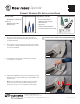
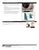
INSTALL THE WEBCONNECT MODULE