
Data Sheet
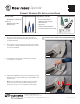

REMOVE THE CIRCUIT BOARD
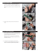
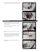
5. Turn the Circuit Board over and unplug the three
connectors: 4-pin (DFI - Drawer Full Indicator), 6-pin
(Motor and power), and the 8-pin (Hall E ect sensor).
Make sure to pull the connector from the base of the
wire.
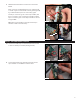
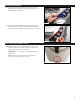
6. Peel the Keypad away from the Circuit Board for
reuse.
7. Attach the Keypad to the new Circuit Board by sliding
the long edge of the Circuit Board under the rubber
lip, then working your way around the perimeter until
the Keypad frames the Circuit Board.
Note: If you think you may have confused the new
Circuit Board for Connect with the original one, see
Figure 30 on Page 8.
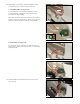
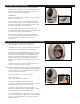
8. From the front of the Keypad, press the three
connection points through the holes on the Circuit
Board to secure them together (see Figure 8b).
Figure 6
Figure 5
Figure 4
2
Figure 7
Figure 8a
Figure 8b
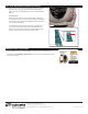
INSTALL THE NEW CIRCUIT BOARD