
Datasheet


RoHS Compliant, ELV Compliant
254
11
Notes:
I
H
: Hold current: maximum current device will pass without interruption in 20°C still air.
I
T
: Trip current: minimum current that will switch the device from low resistance to high resistance in 20°C still air.
V
MAX
Operating : Maximum continuous voltage device can withstand without damage at rated current. This voltage is used for component recognition under UL1434.
V
MAX
Interrupt
: Maximum voltage that can be safely placed across a device in its tripped state. Devices may trip safely under higher level power cross conditions to assist
equipment in meeting the appropriate ITU, UL60950 or GR1089 industry requirements.
I
MAX
Interrupt : Maximum fault current device can withstand without damage at rated operating voltage. This current is used for component recognition under UL1434.
Devices may trip safely under higher level power cross conditions to assist equipment in meeting the appropriate ITU, UL60950 or GR1089 industry requirements.
P
D
: Power dissipated from device when in the tripped state in 20°C still air.
R
MIN
: Minimum resistance of device as supplied at 20°C unless otherwise specified.
R
MAX
: Maximum resistance of device as supplied at 20°C unless otherwise specified.
R
1MAX
: Maximum resistance measured one hour post-trip or post-reflow at 20°C.
* 250V
AC
interrupt products may help equipment pass ITU K.20, K.21 and K.45 recommendations and Telcordia GR-1089 Port Type 2 and 4 requirements.
† 600V
AC
interrupt products may help equipment pass UL60950, TIA-968-A and GR1089 Port Type 1, 3 and 5 requirements.
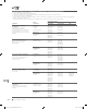
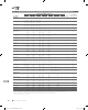
Surface-mount
†
— 600V
AC
TS600/TSM600
TS600-170F 0.170 0.400 60 600 3.0 2.5 1.0 10.0 4.0 9.0 18.0
TS600-200F-RA-B-0.5 0.200 0.400 60 600 3.0 2.5 1.0 12.0 4.0 7.5 13.5
TS600-400F 0.400 1.000 60 600 3.0 2.0 3.0 5.0 0.5 1.5 2.0
TSM600-250F 0.250 0.860 250 600 3.0 2.0 3.0 0.8 1.0 3.5 7.0
TSM600-250F-RA 0.250 0.860 250 600 3.0 2.0 3.0 1.0 1.0 3.0 5.0
TSM600-400F 0.400 1.000 250 600 3.0 2.0 3.0 5.0 0.5 1.5 2.0
Part
Number
I
H
(A)
I
T
(A)
P
D Typ
(W)
Typical Time-to-trip
(A) (s)
R
MIN
(Ω)
R
1MAX
(Ω)
R
MAX
(Ω)
Operating
(V
DC
)
Interrupt
(V
RMS
)
I
MAX
*
†
Interrupt
(A)
V
MAX
C
B
D
A
E
C
to
L
C
L
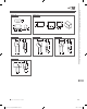
Figure T2
C
B
D
A
E
C
to
L
C
L
Figure T3
B
A
C
Figure T4
C
B
D
E
A
Figure T5
B
D
F
A C
E
Figure T6
B
C
E
A
D
D
Figure T7
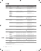
Table T3 Electrical Characteristics for PolySwitch Telecommunications and Networking Devices
Cont’d
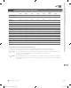
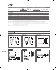
Figures T2-T13 Dimension Figures for PolySwitch Telecommunications and Networking Devices
2013_CP_S11-Poly-8-TeleNetwork.indd 254 8/3/13 10:41 AM