
Datasheet


PolySwitch Resettable Devices – Telecommunications & Networking Devices
RoHS Compliant, ELV Compliant
263
11
Dimension
Description EIA Mark IEC Mark Dimension (mm) Tolerance
Carrier Tape Width W W 18 -0.5/+1.0
Hold Down Tape Width W
4
W
0
5 Min
Top Distance between Tape Edges W
6
W
2
3 Max
Sprocket Hole Position W
5
W
1
9 -0.5/+0.75
Sprocket Hole Diameter D
0
D
0
4 ±0.2
Abcissa to Plane (Straight Lead) H H 18.5 ±3.0
Abcissa to Plane (Kinked Lead)* H
0
H
0
16 -0.5/+0.6
Abcissa to Top H
1
H
1
32.2 Max
Overall Width with Lead Protrusion — C
1
43.2 Max
Overall Width without Lead Protrusion — C
2
42.5 Max
Lead Protrusion L
1
I
1
1.0 Max
Protrusion of Cut-out L L 11 Max
Protrusion beyond Hold Down Tape I
2
I
2
Not Specified —
Sprocket Hole Pitch P
0
P
0
12.7 ±0.3
Device Pitch (TRF250 and TRF600-150) — — 12.7 —
Device Pitch (TRF600-160 - TRF600-400) — — 25.4 —
Pitch Tolerance — — 20 Consecutive ±1
Tape Thickness t t 0.9 Max
Tape Thickness with Splice* t
1
— 2.0 Max
Splice Sprocket Hole Alignment — — 0 ±0.3
Body Lateral Deviation Dh Dh 0 ±1.0
Body Tape Plane Deviation Dp Dp 0 ±1.3
Lead Spacing Plane Deviation DP
1
P
1
0 ±0.7
Lead Spacing* F F 5.08 ±0.6
Reel Width w
2
w 56 Max
Reel Diameter a d 370 Max
Space between Flanges Less Device w
1
— 4.75 ±3.25
Arbor Hole Diameter c f 26 ±12.0
Core Diameter n h 80 Max
Box — — 56/372/372 Max
Consecutive Missing Pieces* — — 3 Max —
Empty Places per Reel* — — Not Specified —
* Differs from EIA specification.
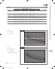
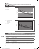
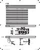
TRF250/TRF600 devices are available in tape and reel packaging per EIA 468-B standard. See Figures T23 and T24 for details.
Table T8
TRF250/TRF600 Tape and Reel Specifications for
PolySwitch Telecommunications and Networking Device
Wave Soldering and Rework Recommendations for PolySwitch Telecommunications Radial-Leaded
Devices
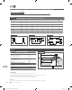
Recommended Wave Soldering
• Soldering temperature profile
Temperature characteristic at component terminal with dual
wave soldering
Rework
• If a device is removed from the board, it should be discarded
and replaced with a new device
300
250
200
150
100
50
0
0 50
10s
245˚C ... 260˚C
100˚C ... 130˚C
Forced cooling
100 150 200 250
Temperature (˚C)
Time (s)
Figure T22
2013_CP_S11-Poly-8-TeleNetwork.indd 263 8/3/13 10:41 AM