
Datasheet

Data Sheets SCRs
©2004 Littelfuse, Inc. E6 - 9 http://www.littelfuse.com
Thyristor Product Catalog +1 972-580-7777
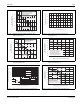
Figure E6.13 Maximum Allowable Case Temperature versus
Average On-state Current (10 A through 20 A)
Figure E6.14 Maximum Allowable Case Temperature versus
Average On-state Current (25 A and 35 A)
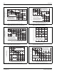
Figure E6.15 Maximum Allowable Case Temperature versus
Average On-state Current (40 A through 70 A)
Figure E6.16 Maximum Allowable Case Temperature versus
Average On-state Current (55 A and 65 A)
Figure E6.17 Normalized dc Holding Current versus Case Temperature
Figure E6.18 Normalized DC Gate-Trigger Current versus
Case Temperature
02468101214
50
60
70
80
90
100
110
120
130
Average On-state Current [I
T(AV)
] – Amps
Maximum Allowable
Case Temperature (T
C
) – ˚C
CURRENT WAVEFORM: Sinusoidal
LOAD: Resistive or Inductive
CONDUCTION ANGLE: 180˚
CASE TEMPERATURE: Measured
as shown on dimensional drawings
20 A TO-220
(Isolated)
15 A TO-220
(Isolated)
10 A TO-220
(Non-isolated)
16 A TO-220 (Non-isolated) and TO-263
0 .4 8 12 16 20 24
50
60
70
80
90
100
110
120
130
Average On-state Current [I
T(AV)
] – Amps
Maximum Allowable Case Temperature (T
C
) – ˚C
CURRENT WAVEFORM: Sinusoidal
LOAD: Resistive or Inductive
CONDUCTION ANGLE: 180˚
CASE TEMPERATURE: Measure as
shown on dimensional drawings
35 A TO-218 (Isolated)
25A TO-220 (Non-isolated)
and TO-263
25A TO-220 (Isolated)
0 1020304050
50
60
70
80
90
100
110
120
130
Average On-state Current [I
T(AV)
] – Amps
Maximum Allowable
Case Temperature (T
C
) – ˚C
CURRENT WAVEFORM: Sinusoidal
LOAD: Resistive or Inductive
CONDUCTION ANGLE: 180˚
CASE TEMPERATURE: Measure as
shown on dimensional drawings
70 A TO-218X
(Non-isolated)
40 A TO-220
(Non-isolated)
and TO-263
55 A TO-218X
(Non-isolated)
65 A TO-218X
(Isolated)
0 102030405
0
50
60
70
80
90
100
110
120
130
Average On-state Current [I
T(AV)
] – Amps
Maximum Allowable
Case Temperature (T
C
) – ˚C
CURRENT WAVEFORM: Sinusoidal
LOAD: Resistive or Inductive
CONDUCTION ANGLE: 180˚
CASE TEMPERATURE: Measure
as shown on dimensional drawings
55 A TO-218AC (Non-isolated) *
*
The R, K, or M package
rating is intended only for high
surge condition use and is not
recommended for >32 A (AV)
continuous current use since narrow
pin lead temperature can exceed PCB
solder melting temperature. J or W
packages are recommended for >32 A
(AV) continuous current requirements.
55 A TO-220
(Non-isolated)
and TO-263
*
65 A TO-218AC
(Isolated) *
-40 -15 +25 +65 +105 +125
0
.5
1.0
1.5
2.0
Case Temperature (T
C
) – ˚C
Ratio of
I
H
I
H
(T
C
= 25 ˚C)
INITIAL ON-STATE CURRENT =
200 mA dc for 1 A to 20 A Devices
and 400 mA dc for 25 A to 70 A Devices
-40 -15 +25 +65 +105 +125
0
0.5
1.0
1.5
2.0
Case Temperature (T
C
) – ˚C
Ratio of
I
GT
I
GT
(T
C
= 25 ˚C)