
Datasheet

Data Sheets SCRs
©2004 Littelfuse, Inc. E6 - 7 http://www.littelfuse.com
Thyristor Product Catalog +1 972-580-7777
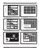
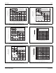
Figure E6.1 Maximum Allowable Ambient Temperature versus
RMS On-state Current
Figure E6.2 Maximum Allowable Ambient Temperature versus
Average On-state Current
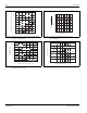
Figure E6.3 Peak Capacitor Discharge Current (6 A through 55 A)
Figure E6.4 Peak Capacitor Discharge Current Derating
(6 A through 55 A)
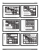
Figure E6.5 Maximum Allowable Case Temperature versus
RMS On-state Current (1 A)
Figure E6.6 Maximum Allowable Case Temperature versus
RMS On-state Current (6 A, 8 A, and 10 A)
20
40
60
80
100
120
0
0.2
0.4 0.6 0.8 1.0 1.2 1.4 1.6
1.8
2.0
2.2
CURRENT WAVEFORM: Sinusoidal
LOAD: Resistive or Inductive
CONDUCTION ANGLE: 180˚
FREE AIR RATING
RMS On-state Current [I
T(RMS)
] – Amps
Maximum Allowable
Ambient Temperature (T
A
) – ˚C
8 A TO-220 (Non-isolated
)
6 A TO-220 (Isolated) and
6 A TO-202 (Types 1 and 3)
1 A TO-92
6 A TO-202
(Types 2 and 4)
and 6 A TO-251
20
40
60
80
100
120
0
0.2
0.4 0.6 0.8 1.0 1.2 1.4
Maximum Allowable
Ambient Temperature (T
A
) – ˚C
Average On-state Current [I
T(AV)
] – Amps
8 A TO-220 (Non-isolated)
6 A TO-220 (Isolated) and
6 A TO-202 (Types 1 and 3)
1 A TO-92
6 A TO-202
(Types 2 and 4)
and 6 A TO-251
CURRENT WAVEFORM: Sinusoidal
LOAD: Resistive or Inductive
CONDUCTION ANGLE: 180˚
FREE AIR RATING
0.5 1.0 2.0 5.0 10 20 50
20
50
100
200
300
1000
Pulse Current Duration (t
w
) – ms
Peak Discharge Current (I
TM
) – Amps
t
w
I
TM
t
w
= 5 times constants
6 A to 10 A Devices
12 A Devices
25 A Devices
55 A Devices
15 A and 16 A
Devices
25 50 75 100 125
0
0.2
0.4
0.6
0.8
1.0
Case Temperature (T
C
) – ˚C
Normalized Peak Current
50
60
70
80
90
100
110
120
130
RMS On-state Current [I
T(RMS)
] – Amps
Maximum Allowable
Case Temperature (T
C
) – ˚C
0 0.4 0.8 1.20.6
CURRENT WAVEFORM: Sinusoidal
LOAD: Resistive or Inductive
CONDUCTION ANGLE: 180˚
CASE TEMPERATURE: Measure as
shown on dimensional drawing
1.00.2
1 A Devices
024681012
50
60
70
80
90
100
110
120
130
CURRENT WAVEFORM: Sinusoidal
LOAD: Resistive or Inductive
CONDUCTION ANGLE: 180º
CASE TEMPERATURE: Measure as
shown on dimensional drawings
RMS On-state Current [I
T(RMS)
] – Amps
Maximum Allowable
Case Temperature (T
C
) – ˚C
8 A TO-220 (Isolated)
and 8 A TO-202
6 A Devices
8 A TO-220 (Non-isolated)
TO-251 and TO-252
10 A TO-220 (Isolated)
and 10 A TO-202