
User Manual

200
Revised: 09/23/13
©2013 Littelfuse, Inc
Specifications are subject to change without notice.
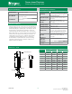
Teccor
®
brand Thyristors
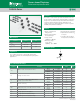
EV Series 0.8 Amp Sensitive SCRs
SxX8xSx Series
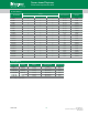
Electrical Characteristics (T
J
= 25°C, unless otherwise specified)
Symbol Description Test Conditions Limit
Value
Unit
SxX8yS1 SxX8yS2 SxX8yS
I
GT
DC Gate Trigger Current
V
D
= 6V
R
L
= 100
MIN. 0.5 1 15 A
MAX. 5 50 200 A
V
GT
DC Gate Trigger Voltage
V
D
= 6V
R
L
= 100
MAX. 0.8 V
V
GRM
Peak Reverse Gate Voltage
I
RG
= 10A
MIN. 5 V
I
H
Holding Current
R
GK
= 1 KΩ
Initial Current = 20mA
MAX. 5 mA
(dv/dt)s
Critical Rate-of-Rise of
Off-State Voltage
T
J
= 125°C
V
D
= V
DRM
/V
RRM
Exp. Waveform
R
GK
=1 k
MIN. 75 V/s
V
GD
Gate Non-Trigger Voltage
V
D
= V
DRM
R
GK
=1 k
T
J
= 25°C
MIN. 0.2 V
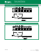
t
q
Turn-Off Time
T
J
= 25°C @ 600 V
R
GK
=1 k
MAX. 30 25 25 s
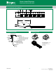
t
gt
Turn-On Time
I
G
=10mA
PW = 15sec
I
T
= 1.6A(pk)
TYP. 2.0 2.0 2.0 s
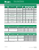
Static Characteristics (T
J
= 25°C, unless otherwise specified)
Symbol Description Test Conditions Limit Value Unit
V
TM
Peak On-State Voltage
I
TM
= 1.6A (pk)
MAX. 1.70 V
I
DRM
Off-State Current, Peak Repetitive
T
J
= 25°C @ V
D
= V
DRM
R
GK
=1 k
MAX. 3 A
T
J
= 125°C @ VD = V
DRM
R
GK
=1 k
MAX. 500 A
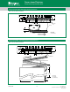
Thermal Resistances
Symbol Description Test Conditions Value Unit
R
th(j-c)
Junction to case (AC)
I
T
= 0.8A
(RMS)
1
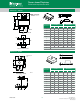
TO-92
75 °C/W
SOT-223
30 °C/W
SOT-89
50 °C/W
R
th(j-a)
Junction to ambient
I
T
= 0.8A
(RMS)
1
TO-92
150 °C/ W
SOT-223
60 °C/W
SOT-89
90 °C/W
1
60Hz AC resistive load condition, 100% conduction.
Note: x = voltage, y = package