
Owner's manual

237
Revised: 09/23/13
©2013 Littelfuse, Inc
Specifications are subject to change without notice.
Teccor
®
brand Thyristors
4 Amp Sensitive SCRs
Sxx04xSx Series
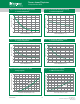
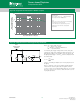
Figure 1: Normalized DC Gate Trigger Current
vs. Junction Temperature
Figure 2: Normalized DC Gate Trigger Voltage
vs. Junction Temperature
0.0
1.0
2.0
3.0
4.0
-40 -15 10 35 60 85 110
Junction Temperature (T
J
) -- (°C)
Ratio of I
GT
/ I
GT
(T
J
= 25°C)
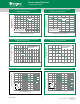
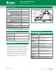
Figure 5: On-State Current vs. On-State
Voltage (Typical)
Figure 6: Power Dissipation (Typical)
vs. RMS On-State Current
Figure 3: Normalized DC Holding Current
vs. Junction Temperature
Figure 4: Normalized DC Latching Current
vs. Junction Temperature
0.0
0.5
1.0
1.5
2.0
-40 -15 10 35 60 85 110
Junction Temperature (T
J
) -- (°C)
Ratio of V
GT
/ V
GT
(T
J
= 25°C)
0.0
0.5
1.0
1.5
2.0
2.5
3.0
-40 -15 10 35 60 85 110
Junction Temperature (T
J
) -- (°C)
Ratio of I
H
/ I
H
(T
J
= 25°C)
0.0
0.5
1.0
1.5
2.0
2.5
3.0
-40 -15 10 35 60 85 110
Junction Temperature (T
J
) -- (°C)
Ratio of I
L
/ I
L
(T
J
= 25°C)
T
J
= 25°C
0
5
10
15
20
25
0.7 0.8 0.9 1.0 1.1 1.2 1.3 1.4 1.5 1.6
Instantaneous On-state Voltage (v) – Volts
Instantaneous On-state Current (i
T
) – Amps
Sxx04VSy
Sxx04DSy
0.0
0.5
1.0
1.5
2.0
2.5
3.0
3.5
4.0
4.5
5.0
5.5
0.0 0.5 1.0 1.5 2.0 2.5 3.0 3.5 4.0
RMS On-State Curre nt [I
T(R MS)
] - (Amps)
Average On-State Power Dissipation [P
D(AV)
] - (Watts)
Sxx04VSy
Sxx04DSy
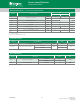
Note: xx or z = voltage, y = sensitivity