
User guide

© 2013 Littelfuse, Inc.
Specifications are subject to change without notice.
Revised: 11/25/13
TVS Diode Arrays (SPA
®
Diodes)
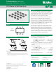
General Purpose ESD Protection - SP724 Series
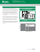
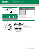
Peak Transient Current Capability for Long Duration Surges
Thepeaktransientcurrentcapabilityisinversely
proportionaltothewidthofthecurrentpulse.Testingwas
donetofullyevaluatetheSP724’sabilitytowithstandlong
durationcurrentpulsesusingthecircuitofFigure4.Figure
5showsthepointofoverstressasdenedbyincreased
leakageinexcessofthedatasheetpublishedlimits.
Thesafeoperatingrangeofthetransientpeakcurrent
shouldbelimitedtonomorethan75%ofthemeasured
overstresslevelforanygivenpulsewidthasshowninthe
curveofFigure5.
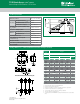
ThetestcircuitofFigure4isshownwithapositivepulse
input.Foranegativepulseinput,the(-)currentpulseinput
goestoanSP724‘IN’inputpinandthe(+)currentpulse
inputgoestotheSP724V-pin.TheV+toV-supplyofthe
SP724mustbeallowedtooat.(i.e.,Itisnottiedtothe
groundreferenceofthecurrentpulsegenerator.)
NotethattwoinputpinsoftheSP724maybeparalleledto
improvecurrent(andESD)capability.Thesustainedpeak
currentcapabilityisincreasedtonearlytwicethatofa
singlepin.
FIGURE 5. TYPICAL SP724 PEAK CURRENT TEST CIRCUIT
WITH A VARIABLE PULSE WIDTH INPUT
+
-
CURRENT
SENSE
VOLTAGE
PROBE
+
-
R
1
~ 10 TYPICAL
SP724
V
X
V
X
ADJ. 10V/A TYPICAL
R
1
(-)
(+)
C1 ~ 100 µF
C
1
VARIABLE TIME DURATION
CURRENT PULSE GENERATOR
123
654
0.001 0.01 0.1 1 10
7
6
5
4
3
2
1
0
100 1000
8
SQUARE WAVE PULSE WIDTH (ms)
PEAK CURRENT (A)
NOTE: TO ENSURE SAFE OPERATION LIMIT
THE MAXIMUM PEAK CURRENT FOR A GIVEN
PULSE WIDTH TO BE NO GREATER THAN 75%
OF THE VALUES SHOWN.
T
A
= 25ºC
V+ TO V-SUPPLY = 15V
ShowingtheMeasuredPointofOverstressinAmperesvs
pulsewidthtimeinmilliseconds
Figure 5: SP724 Typical Nonrepetitive Peak Current
Pulse Capability
Figure 4: Typical SP724 Peak Current Test Circuit
with a Variable Pulse Width Input