
Instruction Manual

© 2013 Littelfuse, Inc.
Specifications are subject to change without notice.
Revised: 04/24/13
TVS Diode Arrays (SPA
®
Diodes)
General Purpose ESD Protection - SP720 Series
Time
Temperature
T
P
T
L
T
S(max)
T
S(min)
25
t
P
t
L
t
S
time to peak temperature
Preheat
P
rehea
t
Ramp-up
R
amp-up
Ramp-down
R
amp-d
o
Critical Zone
T
L to TP
C
ritical Zon
e
T
L
to
T
P
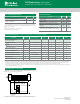
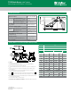
Reflow Condition Pb – Free assembly
Pre Heat
- Temperature Min (T
s(min)
) 150°C
- Temperature Max (T
s(max)
) 200°C
- Time (min to max) (t
s
) 60 – 180 secs
Average ramp up rate (Liquidus) Temp
(T
L
) to peak
5°C/second max
T
S(max)
to T
L
- Ramp-up Rate 5°C/second max
Reflow
- Temperature (T
L
) (Liquidus) 217°C
- Temperature (t
L
) 60 – 150 seconds
Peak Temperature (T
P
) 260
+0/-5
°C
Time within 5°C of actual peak
Temperature (t
p
)
20 – 40 seconds
Ramp-down Rate 5°C/second max
Time 25°C to peak Temperature (T
P
) 8 minutes Max.
Do not exceed 260°C
Soldering Parameters
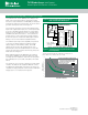
NOTES:
1. Controlling Dimensions: INCH. In case of conflict between English and
Metric dimensions, the inch dimensions control.
2. Dimensioning and tolerancing per ANSI Y14.5M-1982.
3. Symbols are defined in the “MO Series Symbol List” in Section 2.2 of
Publication No. 95.
4. Dimensions A, A1 and L are measured with the package seated in JE-
DEC seating plane gauge GS-3.
5. D, D1, and E1 dimensions do not include mold flash or protrusions.
Mold flash or protrusions shall not exceed 0.010 inch (0.25mm).
6. E and are measured with the leads constrained to be perpendic-
ular to datum .
7. e
B
and e
C
are measured at the lead tips with the leads unconstrained.
e
C
must be zero or greater.
8. B1 maximum dimensions do not include dambar protrusions. Dambar
protrusions shall not exceed 0.010 inch (0.25mm).
9. N is the maximum number of terminal positions.
10. Corner leads (1, N, N/2 and N/2 + 1) for E8.3, E16.3, E18.3, E28.3,
E42.6 will have a B1 dimension of 0.030 - 0.045 inch (0.76 - 1.14mm).
e
A
-C-
C
L
E
e
A
C
e
B
e
C
-B-
E1
INDEX
12 3 N/2
N
AREA
SEATING
BASE
PLANE
PLANE
-C-
D1
B1
B
e
D
D1
A
A2
L
A1
-A-
0.010 (0.25) CAM BS
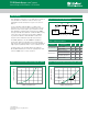
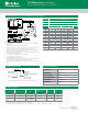
Package PDIP
Pins 16 Lead Dual-in-Line
JEDEC MS-001
Millimeters Inches
Notes
Min Max Min Max
A - 5.33 - 0.210 4
A1 0.39 - 0.015 - 4
A2 2.93 4.95 0.115 0.195 -
B 0.356 0.558 0.014 0.022 -
B1 1. 15 1.77 0.045 0.070 8, 10
C 0.204 0.355 0.008 0.014 -
D 18.66 19.68 0.735 0.775 5
D1 0.13 - 0.005 - 5
E 7.62 8.25 0.300 0.325 6
E1 6.10 7. 1 1 0.240 0.280 5
e 2.54 BSC 0.100 BSC -
e
A
7.62 BSC 0.300 BSC 6
e
B
- 10.92 - 0.430 7
L 2.93 3.81 0.115 0.150 4
N 16 16 9
Notes:
1. Controlling Dimensions: INCH. in case of conflict between English and Metric
dimensions, the inch dimensions control.
2. Dimensioning and tolerancing per ANSI Y14.5M-1982.
3. Symbols are defined in the “MO Series Symbol List” in Section 2.2 of Publication No.
95.
4. Dimensions A, A1 and L are measured with the package seated in JE-DEC seating
plane gauge GS-3.
5. D, D1, and E1 dimensions do not include mold flash or protrusions. Mold flash or
protrusions shall not exceed 0.010 inch (0.25mm).
6. E and e
A
are measured with the leads constrained to be perpendicular to datum -C- .
7. e
B
and e
C
are measured at the lead tips with the leads unconstrained. e
C
must be zero
or greater.
8. B1 maximum dimensions do not include dambar protrusions. Dambar protrusions shall
not exceed 0.010 inch (0.25mm).
9. N is the maximum number of terminal positions.
10. Corner leads (1, N, N/2 and N/2 + 1) for E8.3, E16.3, E18.3, E28.3, E42.6 will have a B1
dimension of 0.030 - 0.045 inch (0.76 - 1.14mm).
Package Dimensions Dual-In-Line Plastic Packages (PDIP)