
Owner manual

©2013 Littelfuse, Inc.
Specifications are subject to change without notice.
Revised: 11/18/13
Transient Voltage Suppression Diodes
50
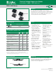
Surface Mount – 3000W > SMDJ-HRA series
SMDJ-HRA Series
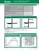
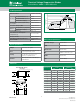
Voltage Transients
Time
Voltage Across TVS
Current Through TVS
Voltage or Current
Figure 1 - TVS Transients Clamping Waveform
Ratings and Characteristic Curves (T
A
=25°C unless otherwise noted)
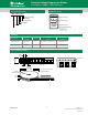
Figure 2 - Peak Pulse Power Rating
0.1
1
10
100
1000
0.001 0.01 0.11
P
PPM
-Peak Pulse Power (KW)
10
0.31x0.31" (8.0x8.0mm)
Copper Pad Area
t
d
-Pulse Width (ms)
P
PPM
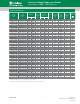
Peak Pulse Power Dissipation -- Max power dissipation
V
R
Stand-off Voltage -- Maximum voltage that can be applied to the TVS without operation
V
BR
Breakdown Voltage -- Maximum current that flows though the TVS at a specified test current (I
T
)
V
C
Clamping Voltage -- Peak voltage measured across the suppressor at a specified Ippm (peak impulse current)
I
R
Reverse Leakage Current -- Current measured at V
R
V
F
Forward Voltage Drop for Uni-directional
continues on next page.
3
Screen Process
100% Vision Inspection MIL-STD-750 method 2074
100% High Temperature Storage Life (168hrs,150°C) MIL-STD-750 method 1031
100% X-RAY inspection MIL-STD-750 method 2076
100% Temperature Cycle Test (-55 to150°C, 20 cycles, dwell time 15 min) MIL-STD-750 method 1051
100% Reflow (2X) JEDECJ-STD-020
100% Surge Test (2x) MIL-STD-750 method 4066
100% HTRB 150°C Bias=VR(80% breakdown voltage, 96hrs, and each
direction at 96 hrs for Bi-directional products)
MIL–STD–750method1038
Final Electrical Test( 100% 3 sigma limit, 100% dynamic test and PAT
limit)
MIL-STD-750 method 4016.4021.4011
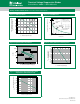
Vc
V
BR
VR
IR
IT
Ipp
V
Uni-directional
VF
Vc
V
BR
VR
IR
IT
Ipp
V
Vc
V
BR
VR
Ipp
IR
IT
Bi-directional
I-V Curve Characteristics
Note: Up-screen program can be specified by customer’s request via contacting Littlefuse service