
Instruction Manual
SIDACtor
®
Protection Thyristors
61
Revised: December 11, 2012
© 2012 Littelfuse, Inc.
Specifications are subject to change without notice.
Please refer to www.littelfuse.com for current information.
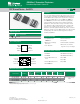
Broadband Optimized™ Protection
SEP Biased Series
Parameter Name Test Conditions Value Units
I
TSM
Maximum non-repetitive
on-state current, 50/60 Hz
0.5s 6.5
A
1s 4.6
2s 3.4
5s 2.3
30s 1.3
900s 0.73
50/60 Hz Ratings
Series
I
PP
I
TSM
2x10μs 1.2x50μs/8x20μs 10x700/5x310μs 10x1000μs
600V
RMS
1 cycle
A min A min A min A min
A
RMS
C 500 400 200 100 30
Surge Ratings
Package Symbol Parameter Value Unit
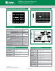
5x6 QFN
T
J
Junction Temperature UP °C
T
STG
Storage Temperature Range UP °C
R
0JA
Thermal Resistance: Junction to Ambient 100 °C/W
Thermal Considerations
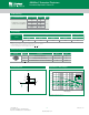
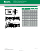
I
H
I
T
I
S
I
DRM
V
DRM
V
T
+
V
-V
+I
-I
V
S
V-I Characteristics
Notes:
- Peak pulse current rating (I
PP
) is repetitive and guaranteed for the life of the product.
- I
PP
SBUJOHTBQQMJDBCMFPWFSUFNQFSBUVSFSBOHFPG$UP$
- The device must initially be in thermal equilibrium with -40°C < T
J
<¡$
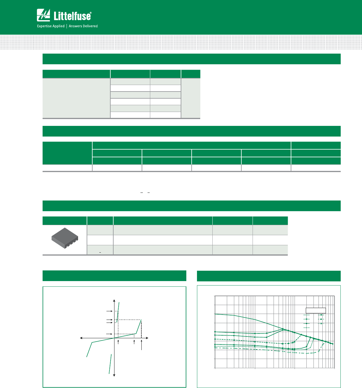
0
5
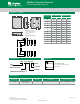
10
15
20
25
30
35
40
0.1 1 10 100
Capacitance (pF)
0V 3.3V
5V 12V
24V 30V
50V
Bias Voltage
Line Voltage (V)
Capacitance vs. Bias Voltage*
* Bias voltage must be lower than V
DRM