
Manual

SIDACtor
®
Protection Thyristors
32
Revised: 09/26/13
© 2013 Littelfuse, Inc.
Specifications are subject to change without notice.
Broadband Optimized™ Protection
SDP Biased Series 5x6QFN
-8
-40 -20 020406080100 120140 160
-6
-4
0
2
4
6
8
10
12
14
Junction Temperature (T
J
) – °C
Percent of V
S
Change – %
25 °C
25°C
Case Temperature (T
C
) - ºC
2.0
1.8
1.6
1.4
1.2
1.0
0.8
0.6
0.4
-40 -20 020406080100 120140 160
Ratio of
I
H
I
H
(T
C
= 25ºC)
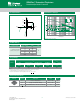
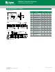
Normalized V
S
Change vs. Junction Temperature
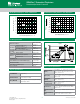
Normalized DC Holding Current vs. Case Temperature
Soldering Parameters
Physical Specifications
Environmental Specifications
Lead Material Copper Alloy
Terminal Finish 100% Matte-Tin Plated
Body Material
UL recognized epoxy meeting flammability
classification 94V-0
High Temp Voltage
Blocking
80% Rated V
DRM
(V
AC
Peak
)+125°Cor+150°C,
504 or 1008 hrs. MIL-STD-750 (Method 1040)
JEDEC, JESD22-A-101
Temp Cycling
-65°Cto+150°C,15min.dwell,10upto100
cycles. MIL-STD-750 (Method 1051) EIA/JEDEC,
JESD22-A104
Biased Temp &
Humidity
52 V
DC
(+85°C)85%RH,504upto1008hrs.EIA/
JEDEC, JESD22-A-101
High Temp Storage
+150°C1008hrs.MIL-STD-750(Method1031)
JEDEC, JESD22-A-101
Low Temp Storage -65°C, 1008 hrs.
Thermal Shock
0°Cto+100°C,5min.dwell,10sec.transfer,
10 cycles. MIL-STD-750 (Method 1056) JEDEC,
JESD22-A-106
Resistance to Solder
Heat
+260°C,30secs.MIL-STD-750(Method2031)
Moisture Sensitivity
Level
85%RH,+85°C,168hrs.,3reowcycles
(+260°CPeak).JEDEC-J-STD-020,Level1
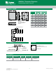
Reflow Condition
Pb-Free assembly
(see Fig. 1)
Pre Heat
- Temperature Min (T
s(min)
)
+150°C
- Temperature Max (T
s(max)
)
+200°C
- Time (Min to Max) (t
s
)
60-180 secs.
Average ramp up rate (Liquidus Temp (T
L
)
to peak)
3°C/sec. Max.
T
S(max)
to T
L
- Ramp-up Rate
3°C/sec. Max.
Reflow
- Temperature (T
L
) (Liquidus)
+217°C
- Temperature (t
L
)
60-150 secs.
Peak Temp (T
P
) +260(+0/-5)°C
Time within 5°C of actual Peak Temp (t
p
)
30 secs. Max.
Ramp-down Rate 6°C/sec. Max.
Time 25°C to Peak Temp (T
P
)
8 min. Max.
Do not exceed +260°C
Time
Temperature
T
P
T
L
T
S(max)
T
S(min)
25
t
P
t
L
t
S
time to peak temperature
(t 25ºC to peak)
Ramp-down
Ramp-up
Preheat
Critical Zone
T
L
to T
P
Figure 1
Time
Temperature
T
P
T
L
T
S(max)
T
S(min)
25
t
P
t
L
t
S
time to peak temperature
(t 25ºC to peak)
Ramp-down
Ramp-up
Preheat
Critical Zone
T
L
to T
P
Figure 1