
User guide

82
Revised: 09/23/13
©2013 Littelfuse, Inc
Specifications are subject to change without notice.
Teccor
®
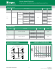
brand Thyristors
8 Amp Sensitive, Standard & Alternistor (High Commutation) Triacs
Lxx08xx & Qxx08xx & Qxx08xHx Series
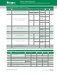
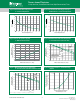
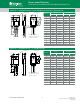
Figure 3: Normalized DC Holding Current
vs. Junction Temperature
Figure 4: Normalized DC Gate Trigger Voltage for
All Quadrants vs. Junction Temperature
Junction Temperature (T
J
)- ºC
-65 -40 -15 10 35 60 85 11 0 1 2 5
0.0
Ratio of
I
H
I
H
(T
J
= 25°C)
0.5
1.0
1.5
2.0
2.5
3.0
3.5
Junction Temperature (T
J
)- ºC
Ratio of
V
GT
V
GT
(T
J
= 25°C)
-65 -40 -15 10 35 60 85 11 0 1 2 5
0.0
0.5
1.0
1.5
2.0
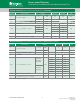
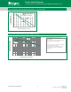
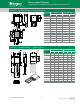
Figure 7: Maximum Allowable Case Temperature
vs. On-State Current (Standard / Alternistor Triac)
Figure 8: On-State Current vs. On-State Voltage
(Typical)
0.6 0.8 1.0 1.2 1.4 1.6
20
16
12
8
4
0
T
C
= 25°C
Postitive or Negative Instantaneous
On-State Voltage (v
T
) - Volts
Postitive or Negative Instantaneous
On-State Current (i
T
) - Amps
RMS On-State Current (I
T(RMS)
) - Amps
0246810
0
2
4
6
8
10
12
14
16
18
Average On-State
Power Dissipation (P
D(AV)
) - Watts
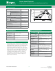
Figure 5: Power Dissipation (Typical)
vs. RMS On-State Current
Figure 6: Maximum Allowable Case Temperature
vs. On-State Current (Sensitive Triac)
RMS On-State Current (I
T(RMS)
) - Amps
012345 678
60
65
70
75
80
85
90
95
100
105
110
Maximum Allowable
Case Temperature (T
C
) - °C
Lxx08Vy
Lxx08Dy
Lxx08Ry
Lxx08Ly
CURRENT WAVEFORM: Sinusoidal
LOAD: Resistive or Inductive
CONDUCTION ANGLE: 360
CASE TEMPERATURE: Measured as shown on
Dimensional Drawings
RMS On-State Current (I
T(RMS)
) - Amps
60
70
80
90
100
11 0
120
130
Maximum Allowable
Case Temperature (T
C
) - °C
012345 678
Qxx08Lyy
Qxx08Ryy
Qxx08Nyy
Qxx08Vyy
Qxx08Dyy
Note: xx = voltage, x = package, y = sensitivity, yy = type & sensitivity