
User guide


56
Revised: 09/23/13
©2013 Littelfuse, Inc
Specifications are subject to change without notice.
Teccor
®
brand Thyristors
4 Amp Sensitive & Standard Triacs
Lxx04xx & Qxx04xx Series
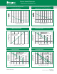
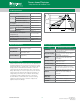
Figure 3: Normalized DC Holding Current
vs. Junction Temperature
Junction Temperature (T
J
)- ºC
Ratio of
I
H
I
H
(T
J
= 25°C)
110 12585603510-40-40-65
4.0
0.0
1.0
2.0
3.0
Figure 4: Normalized DC Gate Trigger Voltage for
All Quadrants vs. Junction Temperature
Junction Temperature (T
J
)- ºC
Ratio of
V
GT
V
GT
(T
J
= 25°C)
110 12585603510-40-40-65
2.0
0.0
0.5
1.0
1.5
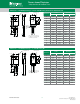
RMS On-State Current (I
T(RMS)
) - Amps
5.04.02.0 3.01.00.0
0.0
Average On-State
Power Dissipation (P
D(AV)
) - Watts
2.0
4.0
CURRENT WAVE FORM: Sinusoidal
LOAD: Resistive or Inductive
CONDUCTION ANGLE: 360°
3.0
1.0
Figure 5: Power Dissipation (Typical)
vs. RMS On-State Current
Figure 6: Maximum Allowable Case Temperature
vs. On-State Current
RMS On-State Current (I
T(RMS)
) - Amps
6345210
Maximum Allowable
Case Temperature (T
C
) - °C
110
Lxx04Ly
Lxx04Dy
CURRENT WAVE FORM: Sinusoidal
LOAD: Resistive or Inductive
CONDUCTION ANGLE: 360°
CASE TEMPERATURE: Measured as shown
on Dimensional Drawing
70
60
75
80
85
90
95
100
105
65
Lxx04Vyz
Lxx04Ry
LXX04Vy
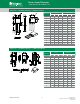
Figure 8: Maximum Allowable Ambient Temperature
vs. On-State Current
RMS On-State Current [I
T(RMS)
] - Amps
2.01. 0 1. 2 1.4 1.6 1. 80.6 0.80.40.20.0
120
100
80
60
40
20
Maximum Allowable
Ambient Temperature (T
A
) - °C
CURRENT WAVEFORM: Sinusoidal
LOAD: Resistive or Inductive
CONDUCTION ANGLE: 360°
FREE AIR RATING – NO HEATSINK
L/Qxx04Vy
Qxx04Ly
Qxx04Ry
Lxx04Ly
Figure 7: Maximum Allowable Case Temperature
vs. On-State Current
RMS On-State Current (I
T(RMS)
) - Amps
6345210
Maximum Allowable
Case Temperature (T
C
) - °C
110
Lxx04Ly
Lxx04Dy
CURRENT WAVE FORM: Sinusoidal
LOAD: Resistive or Inductive
CONDUCTION ANGLE: 360°
CASE TEMPERATURE: Measured as shown
on Dimensional Drawing
70
60
75
80
85
90
95
100
105
65
Lxx04Vyz
Lxx04Ry
LXX04Vy
Note: xx = voltage, y = sensitivity