
Instruction Manual

3
Revised: January 25, 2013 08:34 AM
©2013 Littelfuse, Inc
Specifications are subject to change without notice.
Please refer to http://www.littelfuse.com for current information.
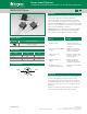
Teccor
®
brand Thyristors
12 Amp Alternistor (High Communitation) Triac for LED dimmer Application
Q6012LH1LED series
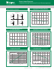
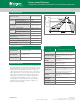
Figure 2: Normalized DC Gate Trigger Current for
All Quadrants vs. Junction Temperature
0.0
1.0
2.0
3.0
4.0
Junction Temperature (T
J
) - C
Ratio of I
GT
/ I
GT
(T
J
= 25 ºC)
-65 -40 -15 10 35 60 85 110
Figure 1: Definition of Quadrants
Note: Alternistors will not operate in QIV
MT2 POSITIVE
(Positive Half Cycle)
MT2 NEGATIVE
(Negative Half Cycle)
MT1
MT2
+ I
GT
REF
QII
MT1
I
GT
GATE
MT2
REF
MT1
MT2
REF
MT1
MT2
REF
QI
QIV
QIII
ALL POLARITIES ARE REFERENCED TO MT1
(-)
I
GT
GATE
(+)
I
GT
-
I
GT
GATE
(-)
I
GT
GATE
(+)
+
-
Figure 3: Normalized DC Holding Current
vs. Junction Temperature
0.0
1.0
2.0
3.0
4.0
-65 -40 -15 10 35 60 85 110
Junction Temperature (T
J
) - ºC
Ratio of I
H
/ I
H
(T
J
= 25ºC)
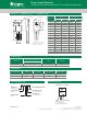
Figure 4: Normalized DC Gate Trigger Voltage for
All Quadrants vs. Junction Temperature
0.0
0.5
1.0
1.5
2.0
-65 -40 -15 10 35 60 85 110
Junction Temperature (T
J
) - ºC
Ratio of V
GT
/ V
GT
(T
J
= 25ºC)
0
2
4
6
8
10
12
14
02468101
21
4
RMS On-State Current [I
T(RMS)
] -- Amps
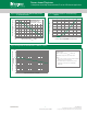
Average On-State Power Dissipation
[P
D(AV)
] -- Watts
CURRENT WAVEFORM: Sinusoidal
LOAD: Resistive or Inductive
CONDUCTION ANGLE: 360°
Figure 5: Power Dissipation (Typical)
vs. RMS On-State Current
Figure 6: Maximum Allowable Case Temperature
vs. On-State Current
60
70
80
90
100
110
120
130
0 2468101
21
4
RMS On-State Current [I
T(RMS)
] - Amps
Maximum Allowable Case Temperature
(T
C
) - °C
CURRENT WAVEFORM: Sinusoidal
LOAD: Resistive or Inductive
CONDUCTION ANGLE: 360°