
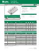
Instruction Manual

©2013 Littelfuse, Inc
Specifications are subject to change without notice.
Revised:08/06/13
Power Module
3
MG06400D-BN4MM
600V IGBT Family
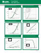
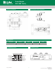
Figure 1: Typical Output Characteristics
I
C
(A)
V
CE
˄V˅
T
Vj
=125°C
T
Vj
=25°C
800
640
480
320
160
0
0
0.4
0.8 1.2
1.6
2.0
2.4
V
GE
=15V
Figure 2: Typical Output Characteristics
V
GE
˄V˅
0
160
I
C
(A)
320
480
640
800
T
Vj
=125°C
T
Vj
=25°C
V
CE
=20V
11 9 01 5 6 7
8
Figure 3: Typical Transfer characteristics
40
60
20
30
10
0
02
6
10 14 18
E
on
E
off
(mJ)
E
on
E
off
R
G
˄Ω˅
V
CC
=300V
I
C
=400A
V
GE
=±15V
T
Vj
=125°C
50
Figure 4: Switching Energy vs. Gate Resistor
0 200
I
C
˄A˅
V
CC
=300V
R
G
=1.5Ω
V
GE
=±15V
T
Vj
=125°C
800600
400
E
off
E
on
0
8
16
40
E
on
E
off
(mJ)
32
24
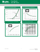
Figure 5: Switching Energy vs. Collector Current Figure 6: Reverse Biased Safe Operating Area
0
200
400
600
800
1000
0100
200
300400 500
600
V
CE
˄V˅
700
R
G
=1.5
Ω
V
GE
=±15V
T
Vj
=125°C
I
C
(A)
V
CE
˄V˅
5.2 0.3 5.3 0.45.00.15.10
I
C
(A)
T
Vj
=125°C
2.04.5 5.0
800
640
480
320
160
0