
Instruction Manual

342
Revised: 09/23/13
©2013 Littelfuse, Inc
Specifications are subject to change without notice.
Teccor
®
brand Thyristors
Standard Bidirectional SIDACs
Kxxxzy Series
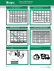
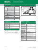
Figure 7: Normalized DC Holding Current
vs. Junction Temperature
0.0
0.5
1.0
1.5
2.0
-40 -15 10 35 60 85 110
Junction Temperature (T
J
) -- °C
Ratio of I
H
/ I
H
(T
J
= 25°C)
125
80
90
100
110
120
130
0.0 0.2 0.4 0.6 0.8 1.
01.2
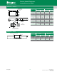
CURRENT WAVEFORM: Sinusoidal - 60Hz
LOAD: Resistive or Inductive
Kxxx0G
Kxxx0S
Kxxx0E
Kxxx2G
RMS On-State Current [I
T(RMS)
] - Amps
Maximum Allowable Lead/Case Temperature
(T
C
) - °C
Figure 8: Maximum Allowable Case Temperature
vs. RMS On-State Current
20
40
60
80
100
120
140
0.0 0.2 0.4 0.6 0.8 1.0
CURRENT WAVEFORM: Sinusoidal - 60Hz
LOAD: Resistive or Inductive
FREE AIR RATING
Kxxx0G
Kxxx0S
Kxxx0E
Kxxx2G
Maximum Allowable Ambient Temperature
(T
A
) - °C
RMS On-State Current [I
T(RMS)
] - Amps
25
Figure 9: Maximum Allowable Ambient Temperature vs.
RMS On-State Current
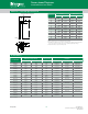
1
10
20 30 40 5060708090100110120130
Repetitive Peak Breakover
Current (I
BO
) Multiplier
Junction Temperature (T
J
) -- °C
Figure 10: Normalized Repetitive Peak Breakover
Current (I
BO
) vs. Junction Temperature
100-250 V ac
60 Hz
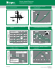
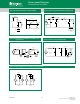
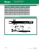
Scope
Push to test
S1
Switch to test
in each direction
100 Ω
1%
Device
Under
Test
S1
Scope Indication
Trace Stops
I
H
I
PK
Figure 11: Dynamic Holding Current Test Circuit for
SIDACs
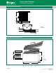
Figure 12: Basic SIDAC Circuit
Load
100-250 Vac
60 Hz
I
H
V
BO
120-145
˚
Conduction
Angle
I
H
I
H
Load Current
V
BO
V
BO