
Installation Guide

© 2016 Littelfuse • LED Lighting SPD Module Design and Installation Guide www.littelfuse.com
LED Lighting Surge Protection Modules
Design and Installation Guide
MOV2
MOV1
SPD
AC Input
I1
I2
I3
LED DRIVER
G
N
L
F1
R1
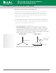
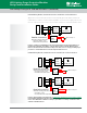
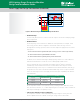
Figure 18. Residual voltage and current can damage an LED driver.
• Residual Voltage
Determined by MOV1; therefore, a varistor with fast response time and low clamping voltage
varistor is preferred.
• Residual Current
The 8×20μs surge current waveform is calibrated to reach peak value (for example, 10kA)
at the surge generator, before it is applied to the luminaire. When the surge current is
discharged from the surge generator, it affects the SPD and power supply unit (PSU) at three
major points.
– I1: The current flow through the SPD (This is major portion of the surge current.)
– I2: The current flow through the MOV in the PSU
– I3: The current flow through the primary circuit in the PSU
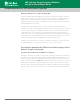
For MOV2, choose an MOV with a higher clamping voltage than the one used for MOV1 to
maximize I1 and minimize I2 so that fuse F1 is not damaged by residual current.
Fuse F1 should be also selected carefully, with a higher melting i
2
t rating to withstand
residual surge current I2+I3. Below fuses are recommended for F1 as they are tested to
withstand 3kA surge current. In poor coordination between MOV1 and MOV2, I2+I3 may go
as high as 30%. These fuses can withstand 3kA residual surge current to help the luminaire
survive the 10kA surge event. Power supply unit thus has higher compatibility with different
SPDs and MOV1.
Part Number Package Rating
8071630 9.2x6.4x12.4mm 6.3A 300V
219005 5x20mm 5A 250V
209007 4.5x14.5mm 7A 350V
477010 5x20mm 10A 500V
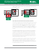
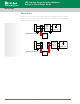
R1, the equivalent resistance of the primary circuitry, including the NTC, EMI filter, rectifier,
PFC, transformer, transistor, etc., could be adjusted higher if necessary in order to minimize I3
and component damage in the primary circuitry.
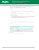
• TVS diode as ultimate protector in LED driver
For components sensitive to and easily damaged by surge voltage or current, place TVS
diodes in parallel with them to absorb “let-through” energy from the SPD module.
Power Supply Unit Design Considerations (continued)
19