
Installation Guide

© 2016 Littelfuse • LED Lighting SPD Module Design and Installation Guide www.littelfuse.com
LED Lighting Surge Protection Modules
Design and Installation Guide
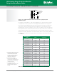
Typically, compliance testing of luminaires involves 20kV/10kA surges in North America and
up to 10kV/5kA
1
in Europe.
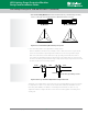
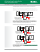
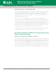
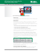
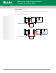
Figure 17. SPD protection schemes that increase the surge immunity of an LED driver.
SPD modules are responsible for protecting luminaires against these high surge levels, which
can occur in outdoor lighting environments. The SPDs use 3-4 parallel- or series-connected
high-surge-withstand (for example, 25mm or 34mm diameter) MOVs across the AC lines,
as shown in the green MOV1 block of Figure 17. As shown in that figure, the MOVs are
installed from Line to Ground, Neutral to Ground and Line to Neutral. For installations in
regions with severe lightning exposure, it is common to use parallel-connected MOVs for the
Line to Neutral leg. This will increase differential mode surge capability and the reliability of
aluminaire.
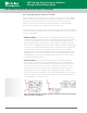
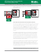
When adding this supplemental protection in front of the LED driver, it is very important
to select (MOV1) characteristics that coordinate with those of the existing (MOV2) device
in the driver. The coordination criterion for MOV1 selection is to make sure these larger
disc MOVs in the SPD module clamp first, thereby taking the brunt of the surge energy
before the smaller (MOV2) disc turns on. This will avoid catastrophic current through the
driver MOV and premature opening of the fuse, which happens if the driver MOV turns on
first. Therefore, the MOVs in the SPD module should have a lower maximum continuous
operating voltage rating than the MOV in the driver.
A certain amount of impedance between the primary SPD and the driver can be beneficial;
perhaps a few microHenries will help ensure proper coordination. For example, a longer
length of cable between the primary SPD and the driver may be sufficient due to the
characteristic impedance of the wire. On the other hand, lead wires on the input side of the
SPD should be minimized to prevent increased clamping voltage in the SPD module due to
the characteristic impedance of those wires.
1 Although North American luminaire standards characterize immunity testing as a 10kV/10kA
requirement, the test setup calls for a 2Ω source impedance, and it is actually a 20kV/10kA requirement.
AC Input
LED DRIVER
SPD
L
N
G
MOV2MOV1
L
AC Input
LED DRIVER
SPD
L
N
G
MOV2
MOV1
Coordination between the SPD and the Power Supply Unit (continued)
17
UltraMOV
™
25S
or TMOV25S
™
Series
UltraMOV
™
25S
or TMOV25S
™
Series