
Installation Guide

© 2016 Littelfuse • LED Lighting SPD Module Design and Installation Guide www.littelfuse.com
LED Lighting Surge Protection Modules
Design and Installation Guide
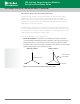
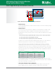
LSP10 Wiring Guide, Parallel Connection with End-of-LifeIndication
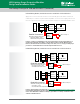
Apply series-connected models of LSP10 Series thermally protected varistor modules (as
indicated by an S suffix in the part number) as parallel connections in the lighting fixture. This
turns the output wires of the series-connected SPD modules into end-of-life indication wires.
L
N
G
SPD
L
L
N/G
or
AC/DC
Power
Supply
LED Module
L
N
+
-
Parallel Connection
LSP10xxxP
L
N
G
SPD
L
L
N/G
or
LED Module
L
N
+
-
LED normally on
Parallel Connection
With LED indicating SPD status
- ON (green): SPD is online
- OFF: SPD needs replacement
LSP10xxxS
AC/DC
Power
Supply
R
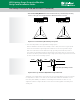
Figure 15. Connect a current limiting resistor and a green LED to form an external indicator of
module status. When the green LED is on, the module is working normally. When the green
LED is off, the module is disconnected from the power circuit, so it is no longer providing surge
protection to downstream devices. It must be replaced with a new one.
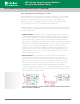
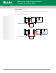
LSP05 Wiring Guide, Parallel Connection with End-of-LifeIndication
L
N
G
SPD
L
L
N/G
or
AC/DC
Power
Supply
LED Module
L
N
+
-
R
LED normally on
Parallel Connection
With LED indicating SPD status
- ON (green): SPD is online
- OFF: SPD needs replacement
LSP05xxxPM
R1
R2
R3
NC
L
N
G
SPD
L
L
N/G
or
LED Module
L
N
+
-
R
LED normally off
Parallel Connection
With LED indicating SPD status
- OFF: SPD is online
- ON (red): SPD needs replacement
LSP05xxxPM
R1
R2
R3
AC/DC
Power
Supply
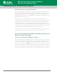
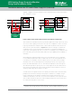
Figure 16. Apply parallel-connected models of LSP05 Series thermally protected varistor modules
(as indicated by a PM suffix in the part number) and connect indication wires to a current-limiting
resistor and a LED indicator. Either a normally-on green LED or a normally-off red LED could be
selected as the LED indicator.
Over-voltage Testing in UL 1449 and IEC 61643-11 (continued)
15