
Datasheet

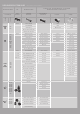


Fuse Options
Fuse
Series
Name
Time Lag (Slo-Blo
®
)
Medium Acting
Fast Acting
Very Fast Acting
Device Range
*
(Operating Current
Options in Amps)
Max. Voltage
Rating
*
(Volts)
Interrupting
Rating at
Max Voltage
Rating
*
(Amps)
Operating
Temperature Range
Agency Approvals
*
RoHS Compliant
Lead Free
Americas Europe Asia
UL
UR
CSA
QPL
CE
VDE
TUV
BSI
Semko
PSE
K
CCC
CQC
312
• 0.01 - 35 250 / 125 / 32 35 - 300
-55°C to +125°C
• • • • • • • •
313
• 0.01 - 30 250 / 125 / 32 35 - 300 • • • • • • • •
314
• 0.125 - 40 250 35 - 1000 • • • • • • • •
322
• 1 - 30 250 / 65 100 - 1000 • • • • •
326
• 0.01 - 30 250 / 125 100 - 600 • • • • • • • •
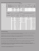
6.3mm X 32mm (3AB / 3AG) Size Fuse Series and Holder Options
Fuseholder Re-Rating
For 25°C ambient temperatures, it is recommended that fuseholders be operated at no more than 60% of the nominal current rating
established using the controlled test conditions specified by Underwriters Laboratories.
The primary objective of these UL test conditions is to specify common test standards necessary for the continued control of
manufactured items intended for protection against fire, etc. A copper dummy fuse is inserted in the fuseholder by Underwriters
Laboratories, and then the current is increased until a certain temperature rise occurs.
The majority of the heat is produced by the contact resistance of the fuseholder clips. This value of current is considered to be the
rated current of the fuseholder, expressed as 100% of rating.
Some of the more common, everyday applications may differ from these UL test conditions as follows: fully enclosed fuseholders,
high contact resistance, air movement, transient spikes, and changes in connecting cable size (diameter and length).
Even small variations from the controlled test conditions can greatly affect the ratings of the fuseholder. For this reason, it is
recommended that fuseholders be de-rated by 40% (operated at no more than 60% of the nominal current rating established
using the Underwriter Laboratories test conditions).
* In some cases for these categories the ratings, agency approvals and specifications vary by part number and
are presented here as ranges representing the whole series.
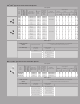
Holder Options
Circuit Connection
Method
Wire Wire Connector Terminals
TH= Thru-Hole Solder SM= Surface Mount Solder ST= Screw Terminal
CT= Wire Connector Terminal RS= Rivet/Screw Hole
Fuse Holder Type
In- Line
Fuse Holders
Panel Mount
Fuse Enclosure
Circuit Board Mount
Fuse Enclosure
Fuse Blocks Fuse Clips
150322 342006 Watertight TH 345101 Shocksafe CT 354 Series RS 101001 / 101002
150 Series 342021 (FHN26W) Water Tight TH 354101-GY ST 356 Series RS 101003 / 102064
155 Series 342024 (FHN26G2) Drip Proof TH 810 Series ST 359 Series TH 102071 / 102074
LHFB Series 342025 (FHN20G) Drip Proof TH 811 Series TH 102076 / 102078
346877 Flip Top TH 814 Series TH 102079 / 102080
340 Series RF Shielded / Watertight TH 862 Series RS 121001 / 121002
342 Series Traditional RS 121004
344 Series Snap / Panel Mount TH 100058 / 122083
345 Series Int. Shocksafe (old) TH 122087 / 122088
3453 Series Int. Shocksafe TH 122090 / 122093
348 Series Snap Mount TH 10207101009
800 Series Shocksafe TH 51800001009
801 / 802 / 803-01 Series
860 Series