
Installation Guide


Part Number: RJ521354 REV C
Revision Date: 11-28-18
Installation Instructions
TWP-LED
Lithonia Lighting Outdoor • One Lithonia Way • Conyers, Georgia 30012
Phone: 800-279-8041 • Fax: 770.918.1209 • www.lithonia.com
© 2011 Acuity Brands Lighting, Inc. All rights reserved.
DELIVERY: Upon receipt of xture and accessories (packed separately), thoroughly inspect
for any freight damage. All damage should be reported to the delivery carrier. Compare
the catalog description listed on the packing slip with the xture label on the inside of
the housing to be sure you have received the correct merchandise.
This device complies with Part 15 of the FCC Rules. Operation is subject to the following
two conditions: (1) this device may not cause harmful interference, and (2) this device
must accept any interference received, including interference that may cause undesired
operation.
Outlet box mounting:
1. Loosen the 2 captive screws in the front housing and remove front cover from xture.
2. Remove electrical splice compartment cover. Keep (2) 8-32 screws for reinstallation.
3. Remove center knock out and feed wires through.
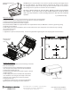
4. Mount xture using dimensions shown in Figure A.
4a. If provided with an ALO device, adjust the dial to the required lumen level (use ALO table as reference), by turning it using
a small at head screwdriver.
5. Make supply connections. Reinstall the (2) 8-32 screws and electrical splice component cover removed in step 2, making
sure no wires are pinched.
6. Replace front cover.
7. Tighten the 2 captive screws (30-35in lbs). Do not over tighten. Over tightening will cause stripping and void all warranties.
Condulet Tee mounting:
1. Loosen the 2 captive screws in the front housing and remove
front cover from xture.
2. Remove electrical splice compartment cover and driver
cover. Keep (2) 8-32 and (2) 10-24 screws for reinstallation.
3. Remove top conduit cover disc.
4. Mount xture using dimensions shown in Figure A. Thread
conduit into xture.
5. Make supply connections. Reinstall both compartment
cover and driver cover using (2) 8-32 and (2) 10-24 screws
removed in step 2, making sure no wires are pinched.
6. Replace front cover.
7. Tighten the 2 captive screws. Do not over tighten. Over
tightening will cause stripping and void all warranties.
7/8” KO
3/8” KO (3)
5”
1-13/16”
4-1/4”
2-1/2”
2-7/8”
15-1/4”
15-3/4”
Conduit cover disc
Electrical splice
compartment
cover
5 year limited warranty