
Installation Guide

13. Mount remaining fi xture(s) as stated in the previous steps with included
Row Connector (11) or 18” Linking Cord.
Note: If Linking fi xtures with included Row Connector (11), insert connector
into previoulsy installed fi xture and connect next fi xture to connector. While
supporting fi xture- mark hole locations for mouting screws.
To route your fi xtures around a corner, simply install fi xtures near the corner,
and use optional 18” Linking Cord to attach the remaining fi xtures in the chain.
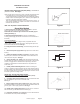
Note: One end of fi xture contains a “Keyed” port (6). Make sure the slotted
end of connector is being installed into the end. See Fig. 6.
14. Once all fi xtures have been installed- reinstall Port covers (9) on any
open fi xture ports.
15. Turn on electricity at fuse or circuit breaker box and verify
success of installation.
Power-Cord Method
(For Direct-Wire Installation
See Direct-Wire Method)
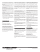
1. If using optional 5’ Power Cord, determine location of your fi rst fi xture.
Make sure the mounting location is within 5 feet of an electrical outlet.
NOTE: The 5’ Power Cord should be attached to the end with Standard Port
(7) only. See Fig. 7. (Located at end opposite of rocker switch).
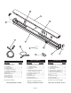
2. Remove LED Cover Assembly (2) by lifting upward on exposed
edges of part. Start in the middle and work outward.
Disconnect Wire connecters (4) from LED Cover Assembly (2) and
Housing Assembly (1).
3. Position the Housing Assembly (1) against the mounting surface
and with a pencil, mark the screw hole locations to be located at the nar-
row section of the keyholes. See Fig. 2.
4. Using a drill with a 1/16” drill bit, make two small pilot holes at the
marked screw hole locations. If drill bit does not encounter a stud or wood
surface, use toggle bolts or suitable fastener depending on structural
conditions. If drill bit does encounter wood surface, use provided #10
wood screw (10).
5. Partially install the Mounting Screws. Position the Housing As-
sembly (1) against the mounting surface with the screw heads through the
keyhole mounting holes. Slide the fi xture until the screw heads are through
the narrow section of the key holes. Finish tightening the screws to secure
the fi xture against the mounting surface.
6. Bundle wires in tight grouping to be out of the way and reconnect
Wire Connectors (4). Reinstall LED Cover Assembly (2).
7. If using only one fi xture skip to Step 10. If there are other fi xtures to be
installed on this chain proceed with Step 8.
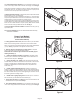
8. Once the fi rst fi xture is mounted, you can install the next fi xture in the
chain. On the end(s) of fi xture to be connected- remove plug cover- See Fig 5.
12. Once the fi rst fi xture is mounted, you can install the next fi xture in the
chain. On the end(s) of fi xture to be connected- remove plug cover- See Fig 5.
Note: Fixture orientation is important- make sure all of the linked fi xtures are
oriented the same way. The linking cord must connect to a Keyed port on
one fi xture and a non-keyed port on the other fi xture.
Page 6
Figure 5
Figure 6
Figure 7