
Large Flush / Semi-Flush Mount Installation Sheet

page 4
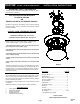
1. Remove fixture components and parts pack(s). Check
that all parts are included. See Figure 1.
2.
Disassemble the fixture by unscrewing the glass diffuser.
See Figure 1.
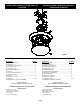
3.
Fully thread (2) #8 x 1½" machine screws into the outer
holes of the crossbar. See Figure 3.
4.
Attach crossbar to junction box with the (2) #8 x 1 machine
screws. (Head of green screw should face downward.)
WIRING AND FIXTURE OPERATION
CAUTION: Connect fixture to supply wires rated for
at least 90° (194°F). Do not use fixture on dimming
circuits.
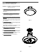
FIGURE 2: TO FLUSH MOUNT FIXTURE
Follow steps 5A to 8A.
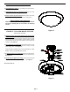
5A. With the power off, hold the fixture firmly and connect
the ground wire from the fixture to the junction box, by
wrapping them under the head of the green ground screw
and securing them to the crossbar. (If house wiring includes
no ground wire consult your local electrical code for approved
methods). See Figure 3.
6A. Use wirenuts to connect the black fixture wire(s) to the
black power supply wire and white fixture wire(s) to white
power supply wire. See Figure 3 .
FOR PROPER CONNECTION, PLACE WIRENUT OVER
WIRES, TWIST CLOCKWISE UNTIL TIGHT.
7A. Align the holes in the fixture pan with the screws extend-
ing from the cross bar previously mounted the junction box.
See Figure 3.
8A. Hold the pan against the ceiling and thread a ball finial
onto each screw until the pan is secure. See Figure 3.
Proceed to Step 11.
Figure 2
Figure 3