
Installation Sheet

U02301 Rev. B
Page 8 of 8
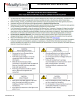
LED IMPORTANT SAFETY INSTRUCTIONS
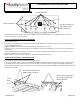
Section J: Wiring – IMP Connector
1) Install fixture based on specified mounting instructions.
2) A 5/8” knock out is located on the IMP access plate. If dimming is required remove access plate and knock out knockout. Pull
dimming wires through access plate and connect to dimming circuit. Reattached access plate to fixture.
3) Snap supply power with IMP male connector (not supplied) into luminaire female IMP connector.
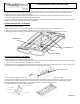
SECTION K: SERVICING
1) Clean fixture as needed. Double check all mounting hardware.
2) After installation, wear protective gloves if the lenses need to be removed
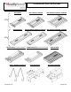
3) The lens snaps around LED channel. To remove lens, carefully pull on outer leg to disengage from LED channel. Continue pulling
outer leg along the fixture length to disengage lens.
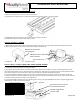
4) To replace the lens snap around LED Channel as shown in the image below.
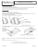
5) To access electrical components, loosen the two captive screws from central channel cover as shown below.
6) Driver Channel Cover will hang on central channel during servicing. Be cautious to avoid bumping fixture as the driver channel
cover can become disengaged.
7) Make any necessary adjustments or driver changes. DO NOT PLACE ELECTRICAL CONNECTIONS ABOVE DRIVER CHANNEL COVER
VENTS
8) Close Driver channel cover and secure using two screws.
Warranty terms are located at the link below:
http://www.acuitybrands.com/resources/terms-and-conditions
LENS
OUTER LEG TO BE
USED FOR REMOVAL
LED CHANNEL
DO NOT PLACE
ELECTRICAL
CONNECTIONS
BEHIND VENTS
DRIVER CHANNEL COVER DURING SERVICING