
Installation Instructions

Page 8 of 9
U4118 Rev A
LED IMPORTANT SAFETY INSTRUCTIONS
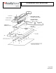
Section J: Wiring – IMP Connector
1) Install fixture based on specified mounting instructions.
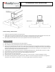
2) A 5/8” knock out is located on the IMP access plate. If dimming is required remove access plate and knock out knockout. Pull
dimming wires through access plate and connect to dimming circuit. Reattached access plate to fixture.
3) Snap supply power with IMP male connector (not supplied) into luminaire female IMP connector.
SECTION K: SERVICING
1) Clean fixture as needed. Double check all mounting hardware.
2) After installation, wear protective gloves if the lens needs to be removed.
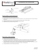
3) The lens rests in the LED channel. To remove lens, remove one of the LED channel’s end plates and slide the lens out. NOTE:
LED housing is made from aluminum sheets. Do not over tighten screws when re-installing the end cover, this will damage the
screw holes. If IBE LED fixture does not come with lens, do not touch the LEDS when servicing the unit. Reinstall the lens and
end cover when cleaning is done. Gloss side of lens faces floor.
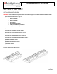
4) If replacing driver, ensure to disconnect all power to the LED high bay being service. Read LED safety instructions on page 1
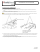
5) To access the driver, remove the two screws at the end opposite the safety cable side.
6) Rotate electrical channel to its side and remove screws holding the channel cover.
7) Slide the channel cover off its securing clips.
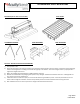
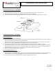
8) Tag wiring before removing the bad driver. Install new driver in the same location. Follow wiring diagram on driver.
9) Use only UL listed 90C (or greater) wiring and connectors. Make sure to push all wiring back into the driver housing before
rotating the driver housing to closed position. Do not let wiring get caught outside the two assemblies.