
Installation Instructions

Page 7 of 9
U4118 Rev A
LED IMPORTANT SAFETY INSTRUCTIONS
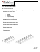
Section G: Installation – External Occupancy Sensor
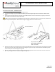
1) External Occupancy sensor will be pre-wired to the fixture.
2) Remove the black wire protection bushing from the hole on the fixture end. This is used to protect sensor wiring from being cut
during transit.
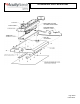
3) Install external occupancy sensor to fixture by snapping into end cap as shown in the fixture below.
4) Rotate/Align the sensor head such that the sensor lens is parallel to the floor.
5) Install fixture based on specified mounting instructions.
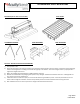
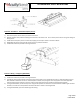
Section I: Wiring – Emergency (PS1555CP)
1) Install fixture based on specified mounting instructions.
2) Input Wires will be located outside of the access plate. Access plate is not removeable. Connect un-switched power to fixture
wires labeled un-switched. Connect un-switched power to white, black, and green wires. Supply wire must meet applicable
electrical codes and be rated for a minimum of 90⁰C. Purple and gray leads are 0-10V (low voltage) dimming leads.
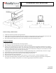
3) If using the PSC1555CP, remove the top cover using the two quarter-turn fasteners. Connect the white indicator light connector
to battery. Connect wires and push back inside the luminaire as shown in the image below.
4) If using the PS1555CP, press the indicator light for testing.