
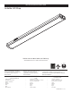
Installation Guide

Row Connector Method
Note: this is for linked satellite units after the main unit is already
installed via the Direct-Wire Method
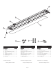
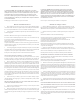
1. Remove di user (2) from housing (1) – locate removal tape attached to
di user near one end of housing; grasp tape and pull upward to release di user
from housing. Carefully remove di user from housing. -See Fig 1
2. Locate the hardware pack– Check that all parts are included. See Page 3.
Note: Toggle bolts or wood screws are not included.
Warning: Safely dispose of packaging materials.
Assistance may be required to support xture during installation.
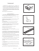
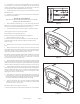
3. Remove 4 keyhole knockouts. -See Fig 5
To remove knockouts: Place standard screwdriver on center of slot and gently
strike with hammer. Grip edge with pliers and ex back and forth until re-
moved. -See Fig 2
4. Remove the port covers (9) on the end caps where the connection will be
made.
5. With the power turned o , insert Row Connector (8) into the previously
installed xture and connect next Fixture Housing (1) to connector. While support-
ing housing – mark the screw hole locations to be located at the narrow section
of the keyholes further from the rst xture (4 total). -See Fig 5.
Note: Fixture orientation is important- make sure all the linked xtures are oriented
the same way by checking that the switches (5) are on the same side. The Row
connector must connect to a Keyed port (6) on one xture and to a non-keyed
port (7) on the other xture. See Figures 6 & 7
6. Remove the Fixture Housing (1) and using a drill with a 1/16” drill bit, make 4
small pilot holes at the marked screw hole locations. If drill bit does not encounter
a stud or wood surface, use toggle bolts or other suitable fasteners depending on
structural conditions. If drill bit does encounter wood surface, use wood screws.
7. Partially install the mounting screws. Position the Fixture Housing against
the mounting surface with the screw heads through the keyhole mounting holes.
Slide the housing until the Row connector is securely connecting the two xtures
and the screw heads are through the narrow section of the key holes. Finish
tightening the screws to secure the housing.
8. Install di user (2) - Note: remove tape from di user prior to installing dif-
fuser. Starting at one end of housing, insert di user slot onto edge of housing.
Carefully squeeze di user to engage opposite side with housing. Continue this
action down length of di user until fully installed onto housing.
9. If there are more xtures to be connected, mount the remaining xture(s)
as stated in the steps 1-8 in this section. Once all xtures have been installed
– reinstall port covers on any open ports.
Note: Max of 6 xtures can be linked on a single row.
10. Turn on electricity at fuse or circuit breaker box and verify success of installation.
10. Install di user (2) - Note: remove tape from di user prior to installing dif-
fuser. Starting at one end of housing, insert di user slot onto edge of housing.
Carefully squeeze di user to engage opposite side with housing. Continue this
action down length of di user until fully installed onto housing.
11. If installing additional satellite units, proceed to follow the Row Connector
Method instructions.
12. If installing only one xture - turn on electricity at fuse or circuit breaker box
and verify success of installation.
Page 6
Figure 5
Figure 6
Figure 7
Continue to Page 8
Screw Hole Location
Keyhole Knockouts