
Installation Guide

PREPARING THE FIXTURE
FOR INSTALLATION
The FMLWL ALO/CCT/LNK fixture has a Switchable CCT
feature and a ALO (Adjustable Lumen Output) feature. Se-
lect from any of the 3000K/4000K/5000K CCT options and
2000lm/3000lm/4000lm light output options. Please refer to
the section CCT/ALO Selection to adjust the switches. The CCT
switch is preset at 4000K and the ALO switch is preset at 3000lm
from the factory.
Note: Turn o power at circuit breaker box!
Direct-Wire Method
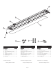
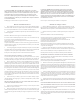
1. Remove di user (2) from housing (1) – locate removal tape attached to dif-
fuser near one end of housing; grasp tape and pull upward to release di user
from housing. Carefully remove di user from housing. -See Fig 1.
2. Locate the hardware pack – Check that all parts are included. See Page (3).
Warning: Safely dispose of packaging materials.
The Main Unit in a chain or a single unit is required to be installed on a standard
ceiling junction box (hardware included).
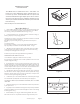
Depending on your mounting-hole spacing, knockout removal may be re-
quired.
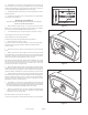
To remove knockouts:
Place standard screwdriver on center of slot and gently strike with hammer.
Grip edge with pliers and ex back and forth until removed. -See Fig 2
3. With the power turned o , thread two Screws (4) into junction box (Note:
screws must be the same distance apart as keyholes on the back of housing
assembly). Do not fully tighten the screws yet.
Assistance may be required to support xture during installation.
WIRING AND FIXTURE OPERATION CAUTION:
Connect xture to supply wires rated for at least 90°C (194°F).
Do not use xture on dimming circuits. Consult a quali ed electrician to ensure
adequate supply wire rating.
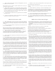
4. Remove Wireway Cover (See Fig 3) by removing two screws securing cover
to Fixture Housing (1). Locate the Black supply wire, the White neutral wire, and
the Green grounding wire. Using a wire stripper, remove the insulating cap from
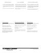
each wire. Strip wire ends to expose 3/8”-7/16” of bare metal. Push all three wires
out the back of the xture through the coined hole (See Fig 4).
5. Hold the Fixture Housing (1) up rmly and connect the green ground wire
from the xture to the bare copper ground wire from the junction box using a
Wirenut (3). (If house wiring does not include a ground wire, consult your local
electrical code for approved grounding methods).
6. Use Wirenuts (3) to connect the black xture wire to the black power supply
wire and the white (neutral) xture wire to the white power supply wire.
FOR PROPER CONNECTION, PLACE WIRENUT OVER WIRES, TWIST CLOCKWISE
UNTIL TIGHT.
7. Hold Fixture Housing (1) in one hand and with the other hand position wires
up into junction box.
8. Align keyholes on back of Fixture Housing with screws previously installed in
junction box. Lift xture up, rotate clockwise and tighten screws to secure Housing
Assembly against ceiling.
9. Reinstall Wireway cover (Fig 3) to Fixture Housing with the two screws.
Note: make sure wires are not pinched between housing and wireway cover.
Coined Hole
Figure 2
Page 4
Figure 4
Continue to page 6
Figure 1
Figure 3
Wireway Cover