
Installation Guide
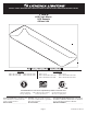

INSTALLATION INSTRUCTIONS
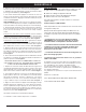
Trouble Shooting Guide
If this fixture fails to operate properly, use the guide below
to diagnose and correct the problem.
Verify that fixture is wired properly.
Verify that fixture is grounded correctly.
The line voltage at the fixture is correct.
If further assistance is required, contact:
Technical Support at: (800) 748-5070
This LED light provides low maintenance service with no
bulbs to change.
Cleaning Diffuser: For best results, diffusers should be
washed with soap or mild detergent. Rinse with clear water
and allow to air dry.
• This fixture is designed for indoor use ONLY
and should not be used in areas with limited
ventilation or high ambient temperatures.
• This fixture is intended to be connected to a
properly installed and grounded UL listed
junction box (not provided) and should be
installed according to NEC and local building
codes.
• Fixture must be secured to mounting surface with
mounting hardware appropriate to your application.
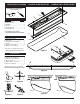
1. Remove fixture components and parts pack(s). Check that all
parts are included. See Page 2.
2. Remove the Screws (4) securing the Wireway Cover (2) to the
Fixture Housing (1) See Figure 1.
3. Remove 7/8” knockout at center of fixture by placing straight
blade screwdriver on knockout and striking sharply with
hammer (Always wear safety glasses when hammering).
Remove slug by flexing back and forth with pliers.
See Figure 2.
WARNING: Before wiring fixture to the power supply, turn
off electricity at fuse or circuit breaker box. Fixture must be
grounded to avoid potential electrical shock and to ensure reli-
able lamp starting.
4. With power turned off, lift fixture Housing (1) to ceiling, centering
over outlet box and parallel to walls. Mark ceiling with pencil for
mounting holes through (2) 1/4” x 3/8” slots. Drill 1/8” pilot hole
at each location.
If drill encounters ceiling joist, Hold fixture up to outlet box and
pull electrical supply wires into the fixture through the knockout
hole. Use wood screw to secure the fixture body the ceiling joist.
See Figure 4.
If drill does not encounter ceiling joist, enlarge hole in ceiling
to accommodate toggle bolt. Hold fixture up to outlet box and pull
electrical supply wires into the fixture through the knockout hole,
insert and tighten toggle bolts. See Figure 3.
5. Ground fixture as follows: Connect the green or bare copper
ground wire from the outlet box under the green ground screw.
If house wiring includes no ground wire, consult your local
electrical code for approved methods. See Figure 5.
6. Connect white fixture wire(s) to white power supply wire with
wirenut. Connect black fixture wire(s) to black power supply
wire with wirenut. See Figure 5.
FOR PROPER CONNECTION, PLACE WIRENUT
OVER WIRES, TWIST CLOCKWISE UNTIL TIGHT.
Note: Make sure no wires are exposed.
7. Replace Wireway Cover (2) under tabs on one side of Fixture
Housing (1). Make sure wires are not pinched between Fixture
Housing and Wireway Cover. Secure ends of wireway cover with
Screws (4). See Figure 1.
8. To install Diffuser (5), lift one side of diffuser almost to ceiling.
Position one side of Diffuser over side flange on Fixture Housing
(1). Lift and shift opposite side of diffuser upward and towards
Fixture Housing until diffuser rests on side flange.
9. Align on center and insert a Locking Bracket (6) at each end
of the Luminaire housing (1), as shown in Figure 6. Fully insert
each bracket to wedge the diffuser against the ceiling. Make sure
the diffuser and the brackets are centered between the ends of the
luminaire housing and are firmly held in place. See Figure 6 & 7.
10. Remove the Brackets to uninstall the Diffuser. See Figure 6.
11. Turn on electricity at fuse or circuit breaker box.
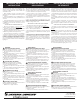
Fixtures that can be used with a dimmer switch.
SEE LIST ON PAGE 1
The fixtures are designed to operate with most standard
Triac Based (Forward Phase-Control or Leading Edge)
dimmer are not compatible with 0-10V dimming systems.
NOTED below is a listed of dimmers that have been tested
with this fixture. This list of dimmers does not imply any
guarantee or warranty of compatibility with a particular
application.
Dimmers that are not listed do not imply non-compatibil-
ity.
Suggested Dimmers
Lutron: DVELV 300P, Skylark 300P, NTELV 300, NLV 600
Leviton: 6633P, 6674P, IPE04,
Page 3