
Installation Guide

Page 4 of 15
UT459804 Rev. B
EPANL/SPANL LED IMPORTANT SAFETY INSTRUCTIONS
If surface box mounting, refer to instruction sheets included with accessory.
In the event of needing to add an emergency battery in the field, refer to the below instructions. Kit numbers can be
found in the accessories section of the spec sheet.
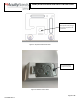
1. Remove the two screws holding the driver cover onto the power plate and slide the driver cover off away from
the lance features on the opposite side shown in Figure 7 and 8.
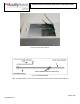
2. Fasten the extension power plate with 3 fasteners into the backplate/recessed housing mating stand offs seen in
Figure 9.
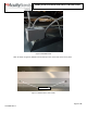
3. Attach the emergency battery to the extension power plate by hooking one side of the battery flange into the
crow’s foot shown in Figure 10 and fasten on the opposite side into the mating hole shown in Figure 11.
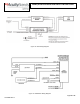
4. Make all the correct electrical connections for the battery shown in Figure 12 & 13.
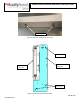
5. Slide new large driver cover onto power plate and fasten into place with 2 screws shown in Figure 14.
6. Make remaining electrical connections in accordance with local and state code with the grid power off.
7. Reinstall the access plate and fasten screw in place like shown in Figure 3.
8. Test switch/pilot light must be mounted in an adjacent ceiling tile. It cannot be mounted to the fixture.
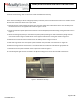
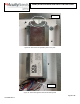
Figure 1: Attached T-Bar Clip