
Installation Guide

Page 3 of 15
UT459804 Rev. B
EPANL/SPANL LED IMPORTANT SAFETY INSTRUCTIONS
THIS PRODUCT MUST BE INSTALLED IN ACCORDANCE WITH THE APPLICABLE INSTALLATION
CODE BY A PERSON FAMILIAR WITH THE CONSTRUCTION AND OPERATION OF THE PRODUCT
AND THE HAZARDS INVOLVED
CE PRODUIT DOIT ÊTRE INSTALLÉ SELON LE CODE D’INSTALLATION PERTINENT, PAR UNE
PERSONNE QUI CONNAÎT BIEN LE PRODUIT ET SON FONCTIONNEMENT AINSI QUE LES
RISQUES INHÉRENTS
Installation Instructions
**Caution: MAKE SURE LUMINAIRE IS MOUNTED TO A SECURE STRUCTURE. USE APPROPRIATE MOUNTING
HARDWARE TO INSTALL FIXTURE RATED FOR YOUR APPLICATION. FAILURE TO MOUNT FIXTURE CORRECTLY
COULD RESULT IN SERIOUS INJURY.
ABOVE CEILING ACCESS REQUIRED
KEEP THESE INSTALLATION INSTRUCTIONS / CONSERVEZ CES INSTRUCTIONS D'INSTALLATION
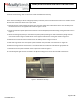
If recess mounting:
1. Place the fixture in the appropriate T-Bar ceiling structure.
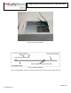
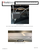
2. From above ceiling, bend the attached T-Bar clips over the T-Bar ceiling on all 4 corners to secure the fixture to
the T-Bar ceiling as shown in Figure 1. For suspension mounting, refer to Figure 2, and instructions provided with
aircraft cable accessory.
a. Refrain from bending the t-bar clips multiple times prior to installation to prevent damage.
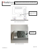
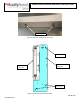
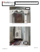
3. Using a screwdriver (not supplied), remove access plate as shown in Figures 3 & 4, with grid power OFF make
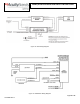
electrical connections from supply and properly ground as local codes dictate (refer to Figure 5).
a. Green wire – Ground
b. White wire – Neutral line in
c. Black wire – Hot line in
4. If the dimming leads (purple & gray) aren’t being used, cap them off (if not already done). Dimming leads are for
low voltage dimming only.
a. Purple wire – 0-10V (+) (can be capped off if not in use)
b. Gray wire – 0-10V (-) (can be capped off if not in use)
5. Reinstall access plate with screwdriver.