
Installation Guide

4. If remote fi xtures are to be connected to the equipment extend the remote circuit in accordance with Article 700 and 720 of the National Electric
Code (NEC) and connect to the YELLOW and VIOLET leads coming out of the unit.
CAUTION: The minimum wire size required by the NEC is 12 gauge copper or equivalent. Your installation may require larger sized wire to ensure
the voltage drop DOES NOT exceed 5%. Do not exceed the total output rating of the equipment including any additional mounted heads.
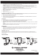
5. Install and connect the battery. Refer to wiring diagram below. Connect the RED (+) lead from the PC board assembly to the positive (+) terminal on
the battery adn the BLUE (-) lead from the PC board assembly to the negative (-) terminal.
CAUTION: Observe polarity. Failure to connect the battery properly will result in equipment failure and an unsafe condition.
NOTE: The emergency lights will NOT com ON at this time.
6. Energize the unit with AC supply.
7. Replace the unit cover.
8. Adjust and focus the lighting heads as required.
ELT627NY & ELT1250NY only: These units include an additional lamp head. If required, this lamp head can be mounted in between the two
existing heads on the unit. This could be done before, during or after the units installation.
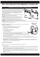
1. Punch out the square mounting hole on the top of the unit.
2. Mount the head securely with the included nut (FIG. A).
3. Connect the yellow and violet wires coming from the circuit board (labeled “REMOTE WIRES”) to the YELLOW and VIOLET wires on the lamp head
using wire nuts or any other appropriate method.
OPERATION:
1. To test the equipment, depress the TEST switch. The charge (LED) indicator will turn OFF and the emergency lights will illuminate.
2. Release the TEST switch. The emergency lights will turn OFF and the charge (LED) indicator will illuminate.
3. The automatic charger will return into action, charging the battery to maintain it in a fully charged state.
NOTE: Allow the battery to charge for a minimum of 24 hours after installation or after a power failure before conducting a 90 minute test (see TESTING
section).
CAUTION: This equipment is furnished with a sophisticated solid state transfer switch which will automatically disconnect the emergency lights from the
battery if the battery has been discharged to the end of its useful output.
MAINTENANCE:
1. BATTERY: The battery supplied in this unit requires no maintenance. Battery must be tested per the latest edition of NFPA 101 Life Safety Code every
30 days for 30 seconds and annually for 90-minutes. Written records of the testing must be kept for examination by the authority having jurisdiction.
Battery must be replaced when it no longer operates the emergency equipment for the complete duration of a 90-minute test.
2. OTHER: Clean lenses and replace lamps as required.
WARRANTY Three Year:
This three year warratny covers any defect in manufacturing, provided the defect develops under normal and proper use. This liability extends only to
replacement of the replacement of the defective part. Labor charges will be honored by the factory only with prior written approval from an authorized Post
Sales representative.
WIRING DIAGRAMS:
One Lithonia Way, Conyers GA 30012
Phone: 800-334-8694
www.lithonia.com
Part #EMCSA00745 Rev. F
2017.06.20
PAGE: 2 of 2