
Installation Guide

Page 5 of 6
912-00214-001 Rev A
LED IMPORTANT SAFETY INSTRUCTIONS
STEP-BY-STEP GUIDE
PREPARING THE FIXTURE FOR INSTALLATION
1. Remove the parts pack and place it in a convenient location during
installation. Check that all parts are included.
2. Inspect the existing mounting location for damage before installing the
new CPHB LED high bay in this location. Ensure mounting structure
is properly sized to support the weight of the fixture.
3. Remove the fixture from packaging and inspect for any damages.
Handle fixture with care.
4. After installation ensure no wires are pinched or caught outside the
fixture housing.
INSTALLATION OF FIXTURE
• This fixture is designed to be Suspended using supplied V-Hangers
and Chain or Surface mount installation with optional Surface Mount
Bracket (THUN)- sold separately. Fixture may also be suspended
using aircraft cable (sold separately).
• Provide suitable hardware that is both in accordance with local
codes and is capable of supporting the full weight of the fixture.
WARNING: Before wiring fixture to the power supply, turn off
electricity at fuse or circuit breaker box.
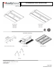
Suspended Installation- (Standard Mounting Method)
1. Locate provided Chains and V-Hangers. Attach Chain to each V-
Hanger by feeding hanger through chain link.
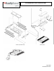
2. Attach the V-Hanger to fixture by hooking the hanger through holes
on the Fixture Housing- See Fig 2.
3. Secure the other end of the chain to structure using hardware rated
for the load.
Make sure the wiring hangers are fully engaged into the side
holes on the fixture housing. If using “S” hooks, make sure all
loops are crimped closed if possible. Make sure wire hanger fits
snuggly into holes of fixture housing.
Supply Wire connections- Make all supply wire connections in
accordance with local electrical codes.
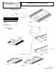
1) Remove access plate screw- see Fig 3 and remove access plate from
Fixture Housing (Input wires from Driver will be attached to the access
plate).
2) Remove the necessary knockout(s) from Access Plate.
3) Secure incoming power supply to access plate with UL Listed
connector. Use only UL listed supply wire (90°C or greater).
4) Make wire connections by connecting bare copper or green supply
wire to green fixture wire. Connect black supply wire to black fixture
wire and white supply wire to white fixture wire with UL Listed wire
nuts (rated 90°C or greater). Purple and gray leads are 0-10V (low
voltage) dimming leads and each wire shall be capped when not being
used.
5) Reinstall Access plate and secure with access plate screw.
Surface Mount Installation- (Requires Surface Mount
Bracket (THUN) - sold separately
1. Attach THUN Surface Mount bracket(s) to structure using hardware
rated for the load.
2. Support fixture while snapping Fixture Housing into THUN bracket(s).
Ensure fixture is balanced.
3. Install supplied nut and lock-washer. Properly tighten nut to secure
THUN bracket around center channel- See Fig 4.
Supply Wire connections- Make all supply wire connections in
accordance with local electrical codes.
4. Remove access plate screw- see Fig 3 and remove access plate
from Fixture Housing (Input wires from Driver will be attached to the
access plate).
5. Remove the necessary knockout(s) from Access Plate.
6. Secure incoming power supply to access plate with UL Listed con-
nector. Use only UL listed supply wire (90°C or greater).
7. Make wire connections by connecting bare copper or green supply
wire to green fixture wire. Connect black supply wire to black fixture
wire and white supply wire to white fixture wire with UL Listed wire
nuts (rated 90°C or greater). Purple and gray leads are 0-10V (low
voltage) dimming leads and each wire shall be capped when not being
used.
8. Reinstall Access plate and secure with access plate screw.
IMP Connector
1. Install fixture based on specified mounting instructions.
2. A 5/8” knock out is located on the IMP access plate. If dimming is
required remove access plate and knock out knockout. Pull dimming
wires through access plate and connect to dimming circuit.
Reattached access plate to fixture.
3. Snap supply power with IMP male connector (not supplied) into
luminaire female IMP connector.
Emergency (PS1055CP/PS1555MCP/ILB-CP20_HE)
1. Install fixture based on specified mounting instructions.
2. If using PS1055CP or PS1555MCP the wiring can be accessed
inside the backpack. If using the ILB-CP20_HE the wiring can be
accessed thru the access plate.
3. Connect switched power to fixture wires labeled switched.
Connect un-switched power to white, black, and green wires.
Supply wire must meet applicable electrical codes and be rated
for a minimum of 90⁰C. Purple and gray leads are 0-10V (low
voltage) dimming leads.
4. If using the ILB-CP20, remove the access plate. Connect the unit
connector to battery AFTER installation is complete.
5. Press the indicator light for testing.
External Occupancy Sensor
1. External Occupancy sensor will be pre-wired to the fixture.
2. Remove the black wire protection bushing from the hole on the
fixture end. This is used to protect sensor wiring from being cut
during transit.
3. Install external occupancy sensor to fixture by snapping into end
cap as shown in Figure 7 below.
4. Rotate/Align the sensor head such that the sensor lens is parallel
to the floor.
5. Install fixture based on specified mounting instructions.
TROUBLE SHOOTING GUIDE
If this fixture fails to operate properly, use the guide below to diagnose
and correct the problem.
• Verify that fixture is wired properly.
• Verify that fixture is grounded correctly.
• The line voltage at the fixture is correct.
If further assistance is required, contact:
Technical Support: (800) 705-SERV (7378)
techsupport-industrial@acuitybrands.com
Limited Warranty and Limitation of Liability
5-year limited warranty. Complete warranty terms located at:
www.acuitybrands.com