
Technical Specifications

900 Northrop Road, Wallingford, CT 06492 • 1.800.PASSIVE • FX 203.269.9621 • www.sensorswitch.com
WARRANTY: Sensor Switch, Inc. warrants these products to be free of defects in manufacture and workmanship for a
period of 60 months. Sensor Switch, Inc., upon prompt notice of such defect, will, at its option, provide a Returned Material
Authorization number and repair or replace returned product.
LIMITATIONS AND EXCLUSIONS: This Warranty is in full lieu of all other representation and expressed and implied
warranties (including the implied warranties of merchantability and tness for use) and under no circumstances shall
Sensor Switch, Inc. be liable for any incidental or consequential property damages or losses.
TS-CMRB-007B
Revised 10.25.2012 © 2012 Sensor Switch
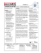
INSTALLATION
WIRING (DO NOT WIRE HOT)
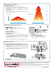
COVERAGE PATTERN
30 20 10 0 ft 10 20 30
9.1 6 3 0 m 3 6 9.1
0 ft
15
30
45
0 m
4.6
9.1
13.7
LOW VIEW
HIGH VIEW
0 ft
15
0 m
4.6
20 10 0 ft 10 20
6 3 0 m 3 6
6 HIGH BAY 360º LENS
• Best choice for 15 to 45 ft (4.57 to 13.72 m) mounting heights
• 15 to 20 ft (4.57 to 6.10 m) radial coverage overlaps area lit by a typical
high bay xture
• Excellent detection of large motion (e.g. walking) up to a 35 ft (10.76
m) mounting height
• Excellent detection of extra large motion (e.g. forklifts) up to a 45 ft
(13.72 m) mounting height
BLK
BLK
WHT
VIO (+)
GRY (-)
[D] Dimming Option
PROGRAMMING
Refer to instruction card IC7.002 for default settings and directions on programming the sensor via the push-button.
PUSH BUTTON
LOCK NUTCHASE NIPPLE KNOCK OUT
FB3
CENTER OF
AISLE
END OF
AISLE
STANDARD WIRING
BLACK* - Line Input
BLACK* - Load Output
WHITE - Neutral
347 VAC OPTION (347)
Black wires are replaced w/ Red wires
INITIAL POWER UP
The sensor’s relay is shipped in a latched closed position so the lights
will come on upon initial power-up. If the lights do not immediately turn
on (initial installation only) the latching relay opened during shipment
and will close within 30 secs.
Note: If the sensor loses power, the internal relay will latch closed.
DIMMING OPTIONS (D, ADC)
VIOLET - Connect to Violet control wire from
0-10 VDC dimmable ballast
GRAY - Connect to Gray common wire from
ballast
*BLACK wires can be reversed
}
• Sensor mounts through a 1/2” knockout hole to a xture or junction box.
• A label kit is included to mask off half of the sensor’s coverage pattern
for end of aisle, or trim the side viewing to create a rectangular pattern
for center of aisle.
• If the sensor’s eld-of-view is partially blocked by the xture housing,
the FB3 Fixture Bracket (not included) can be used to lower the sensor
down to a level where its view is not impaired.