
Technical Specifications

900 Northrop Road, Wallingford, CT 06492 • 1.800.PASSIVE • FX 203.269.9621 • www.sensorswitch.com
WARRANTY: Sensor Switch warrants these products to be free of defects in manufacture and workmanship for a
period of 60 months. Sensor Switch upon prompt notice of such defect, will, at its option, provide a Returned Material
Authorization number and repair or replace returned product.
LIMITATIONS AND EXCLUSIONS: This Warranty is in full lieu of all other representation and expressed and
implied warranties (including the implied warranties of merchantability and tness for use) and under no circumstances
shall Sensor Switch be liable for any incidental or consequential property damages or losses.
TS-CM-005A
Revised 10.11.13 © 2013 Sensor Switch
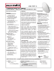
INSTALLATION
WIRING (DO NOT WIRE HOT)
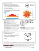
COVERAGE PATTERN
0 ft
9
0 m
2.7
SIDE VIEW
TOP VIEW
12
6
0 ft
6
12
3.7
1.8
0 m
1.8
3.7
12 6 0 ft 6 12
3.7 1.8 0 m 1.8 3.7
STANDARD RANGE 360º LENS WITH MICROPHONICS
Note: Screw axis is
aligned with a long
detection segment
0 ft
9
0 m
2.7
SIDE VIEW
TOP VIEW
12
6
0 ft
6
12
3.7
1.8
0 m
1.8
3.7
12 6 0 ft 6 12
3.7 1.8 0 m 1.8 3.7
• Best choice for small motion (e.g. hand movements) detection
• Viewing angle of 56º in a 360º conical shaped pattern
• Provides 12 ft (3.66 m) radial coverage when mounted to
standard 9 ft (2.74 m) ceiling
• 8 to 15 ft (2.44 to 4.57 m) mounting heights provide 10 to 20 ft
(3.05 to 6.10 m) radial coverage
• Microphonics™ provides overlapping detection of human
activity over the complete PIR coverage area. Advanced
ltering is also utilized to prevent non-occupant noises from
keeping the lights on.
[R] Relay Option
[D, P, ADC] Photocell / Dimming Options
POWER PACK
(PP20)
RED
WHT
BLK
VIO w/ WHT STRIPE (+)
(-)
PUSH BUTTON
PROGRAMMING
Refer to instruction card IC7 for default settings and directions on programming the sensor via the push-button.
• Mount sensor directly to a ceiling tile or a metallic grid (two
self-tapping screws provided)
• Sensor’s mounting holes also align with 3.5” octagon or
single gang handy box (screws not provided)
• Sensor will detect motions crossing segments more
effectively than motions parallel to beams
• For optimal detection, position sensor such that segments
are crossed upon entrance and unable to view outside
the space
• For maximum Microphonics sensitivity avoid locating
sensor near HVAC air diffusers.
STANDARD WIRING
RED - Power Input (12-24 VAC/VDC)
BLACK - Common
WHITE - Occupancy State (high VDC for occupied)
RELAY OPTION (R)
GRAY / BROWN - Connected during occupied state
VIOLET / BROWN - Connected during unoccupied state
Note: Relay is energized during unoccupied state
PHOTOCELL/DIMMING OPTIONS (D, P, ADC)
BLUE - Direct output to power pack for providing photocell
control and/or secondary dim time out. Output is high VDC
with occupancy & low light. Output also held high during
secondary dim time out. For multi-level control, use two
power packs and connect White wire to primary load and
Blue to daylight load.
VIOLET w/ WHITE STRIPE - Connect to 0-10 VDC control
wire (typically Violet) from 0-10 VDC dimmable ballast
GRAY from Ballast - Connect to sensor Black wire