
Installation Sheet


Page 8 of 11
U351 Rev. A
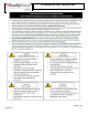
LED IMPORTANT SAFETY INSTRUCTIONS
Section F: Wiring – Emergency (BGTD, PS1050)
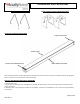
1) Install fixture with Mounting brackets, directly to surface, or with V-hooks. Do not wire.
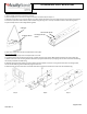
2) The emergency battery pack indicator light must be plugged in during installaion. Remove housing end cap near access plate as
shown in previous instructions.
3) Fixture will be provided with a wiring harness at the access plate end. Attach the two connectors together to activate the battery
pack
2) Connect unswitching power to fixture wires labeled unswitched. Connect switched power to white, black, and green wires. Supply
wire must meet applicable electrical codes and be rated for a minimum of 90⁰C. Purple and gray leads are 0-10V (low voltage)
dimming leads.
SECTION G: SERVICING
1) Clean fixture as needed. Double check all mounting hardware.
2) After installation, wear protective gloves if the lenses need to be removed
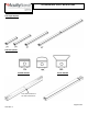
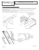
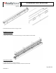
3) The lens snaps into the LED channel. To remove lens, carefully squeeze lens together to disengage from LED channel.
4) To replace the lens snap into LED Channel as shown in the image below.
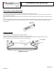
FDL/RDL detachment
LED CHANNEL
Lens
Squeeze together to disengage Lens from LED Channel